| Book |
Page |
Context |
 |
 |
Engine Compartment Cover Panel Assembly 10 67 Compartment Floor Side Panel Assembly 10 67 Headlining 10 68 Removal 10 68 Installation 10 68 Exterior Mouldings 10 69 Rear Quarter Front Reveal Moulding 10 69 Rear |
|
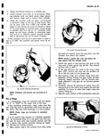 |
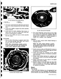
ring travel This I an be done with Tool J 8087 fig 6A 68 Set gauge so that thrust pin must be forced in about y4 to enter gauge in cylinder bore Center gauge ...
exci ss of 005 the cylinder and piston must be replac rd W f Fig 6A 68 Checking Cylinder Bore NOTE Cylinders and pistons are serviced as a unit Pisi m Rings A 1 compression |
|
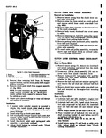 |
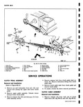
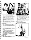
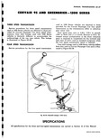
rear cover access to cables 5 Remove retaining nut bolt 17 and pulley spacer 18 fig 68 8 from clutch pulley Remove pulley and spacer from parking brake bracket 6 Remove parking brake and clutch ...
cable cross shaft from ball stud mounted on the engine front mounting bracket Installation Refer to Figure 68 9 1 Lubricate ball stud 23 attached to engine front mounting bracket with a suitable chassis lubricant |
|
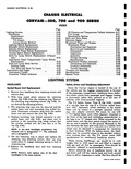 |
Windshield Washer optional 8 66 Description and Operation 8 66 Overhaul Procedures 8 67 Trouble Shooting 8 68 Troubles and Remedies 8 75 Specifications 8 82 Special Tools 8 82 3 SYSTEM Safety Aimer |
|
 |
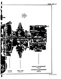
Third 1 00 1 1 44 1 1 00 1 1 55 1 1 00 1 1 68 1 Fourth 1 00 1 1 00 1 1 00 1 Reverse |
|
 |
FOUR SPEED 4 26 1 2 55 1 1 68 1 1 00 1 AUTOMATIC 4 73 1 1 00 1 500 700 AND 900 SERIES THREE SPEED |
|
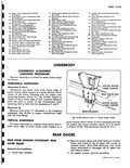 |
Side Rail Panel Rear At Hold Down BS Support Rear 67 Rail Floor Pon Side Mounting Fro 68 Reinforcement No 1 floor Pan Bar 86 Nut Rear Susf 69 Bar No 1 Floor |
|
 |
CLUTCH REAR AXLE Section 68 Section 6C mf 7 UP N NL 0 I us TY yru MANUAL TRANSMISSION Section 6D S ction |
|
 |
PLASTIC PLUG ACCESS HOLE 2 A 3 CLUTCH FORK I 23 22 24 OUTBOARD Fig 68 12 1 Clovis Pin 7 Plain Washer 2 Seal Assembly 8 Idler Lever Bracket 3 Clutch Return Spring Extension |
|
 |
68 4 R moving Clutch Release Bowing 1 Clutch Fork J Ball Stud 2 Release Bearing 4 Axle Housing 4 Disconnect clutch fork from ball stud and remove the clutch release bearing from the clutch |
|
 |
holding cylinder with studs or bolts mounted c t a wooden board as shown in Figure 6A 68 ocedure is outlined under Piston Rings and ylinder Assembly Cran shaft Pulley 40 l emove crankshaft pulley |
|
 |
gear ratios only First speed gear ratio is 4 26 1 2 55 1 in second 1 68 1 in third and 1 1 in fourth Reverse is 4 27 1 Increased torque multiplication |
|
 |
Hold Down 81 Panel Front W 67 Rail Floor Pan Side Rail 82 Extension Fron Front 68 Reinforcement No 1 Floor Pan Bar 83 Panel Front W 69 Bar No 1 Floor |
|
 |
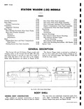
Rampside Pickup VEHICLE DIMENSIONS Greenbrier and Corvan Overall Length 179 7 in Overall Height 68 5 in Overall Width 70 0 in Wheelbase 95 0 in Turning Diameter 42 6 ft Load Compartment Height |
|
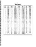 |
035C 39 0 0995 66 0 0330 40 0 0980 67 0 0320 41 0 0960 68 |