| Book |
Page |
Context |
 |
 |
Outside Handle Push Button 10 38 Headlining 10 38 Seats and Seat Compartment Trim 10 39 Front Seat 10 39 Front Seat Assembly 10 39 Seat Adjusters 10 39 Seat Back 10 40 Seat Side |
|
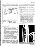 |
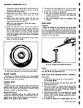
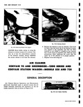
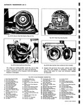
slot in the door inner panel and firmly holds the door trim assembly in positior fig 10 39 1 TRIM AND ASSEMBLY L i f o Ar o o O PLASTIC RETAINER 1 TRIM RETAINNING ...
WATERPROOF NAIL BODY TAPE V I DOOR TRIM ASSEMBLY Fig 10 39 Door Trim Installation Removal and Installation 1 Apply masking tape to door inner panel at trim assembly retainer locations shown in Figure ...
backed waterproof body tape over retainer holE in inner panel as shown in View A Figure 10 39 Make two 2 slits in tape to form an X pattern Check retainer for snug |
|
 |
Outside front Wall to wall right 41 6 ft left 41 3 ft Curb to curb right 39 5 ft left 39 0 ft Inside rear right and left Wall to wall right |
|
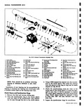 |
seen through the slot in the clutch sleeve 0 J 12 13 1 l4 ls 39 ...
First and Reverse fork Seorings and Spacer 3e Transmission Case 0 Reverse Idler Gear Bearing Race 39 Pipe Plug 2 U e1 31 Reverse Idler Gear Bearing 40 Delent Cop defkel Twrinqlon 41 Detenf |
|
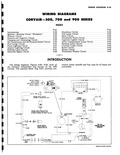 |
WIRING CORVAIR 500 7 11 Page Introduction 8 39 Ignition Starting Circuit Energized 8 39 I Primary Circuit 8 40 Positive and Negative Circuit 8 40 Charging and Generating Circuit 8 40 Oil Temperature |
|
 |
drive the seal as this seal is mounted flush X y V u r Fig 6C 39 Installing Pinion Shaft Front Seal with J 8340 1 Remove the old seal by prying out with ...
seal with non hardening sealer then install new seal using J 8340 as illustrated fig 6C 39 and 40 Pinion Shaft Rear Oil Seal Replacement 1 Drive out old seal with a pin punch inserted |
|
 |
fire wall 4 Disconnect the blower wire and control cables from heater housing see fig 11 39 5 Remove two angle brackets A fig 11 37 from the cross air duct and underbody ...
VALVE CONTROL HEAT CONTROL LEVER APPROX TEMPERATURE s APPROX CONTROL CABLE AIR CONTROL CABLE Fig 11 39 Control Cable Attachment Inspection While the heater housing is removed from the vehicle inspect the seals |
|
 |
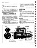
39 40 41 42 Fig 6A 113 Engim 1 Engine Upper Shroud 11 Oil Level Gauge 2 Heater Connection 12 Exhaust Duct Door Shaft 3 Oil Cooler Access Hole Cover 13 Flat Washer 4 Engine ...
Sleeve 37 Engine Cylinder Air Baffle 7 Mounting 38 Engine Rear Shroud l H 8 Lower Retainer 39 Engine Lower Shroud a 9 Rebound Pad Exhaust Duct l H 0 Rear Lower Mounting Rebound Retainer |
|
 |
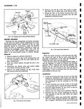
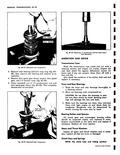
especially careful to check that the drive hub is tightly retained by the snap ring Fig 611 39 Installing Front Pump Shaft Hub Snap Ring Repairs If bronze drive hub is worn remove ...
snap ring fig 6 39 and replace the hub REAR PUMP AND REVERSE PISTON ASSEMBLY Disassembly NOTE All number references in this procedure are to Figure 6E 40 1 Remove the drive gear |
|
 |
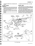
replace steering wheel as outlined in Corvair 500 700 and 900 Section DIRECTION SIGNAL FIG 4 39 Removal 1 Remove steering wheel as outlined in this section 2 Disconnect horn wire from connector under dash ...
remove retaining spring seat and bearing assembly from mast jacket 1 ov O i Fig 4 39 Exploded View of Steering Wheel 3 Disconnect direction signal cable from switch 4 Loosen clamp screw and lift |
|
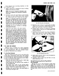 |
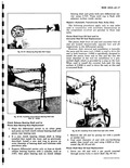
cleaned area to dry Roughen area around injury with hand buffer o wire brush see Figure 3 39 r Fig 3 38 Filling Mole with Sealing Gun 5 Spread an even coating of a good ...
special hot patch clamp Tighten clamp maximum finger tight See Figure 3 40 X10 7 Fig 3 39 Roughening Injury Area 8 Ignite patch material Allow to cool 15 minutes or until cool enough |
|
 |
39 0057 40 0054 41 0052 42 0050 4 0048 44 0046 GES GAGE AMERICAN WIRE or B S GAGE Inches Thickness Inches |
|
 |
035C 39 |
|
 |
servicemen are sufficiently versed in the t adjustment that it will not be covered here Figure 11 39 illustrates cable adjustments dimensions INLET B ASSY 110 WIRE 4CK 8 GRAY i ll v y ONHEATER |
|
 |
Shroud Sheet Metal Station Wagon Seat Front Pan Roar 38 Plate Engine Compartment Baffle Sid Exchanger Opening 39 Plate Rear Cross Bar To Rear Rail Front Lower Exchanger Opening 40 Reinforcemant Rear End Panel |
|
 |
bracket W 19 6 Engine compartment right sid Sedans at a point directly below cen bracket X 39 Engine compartment side rail bolt holes VERTICAL Reference Fig 10 4 Dimension a 135 32 Center |
|
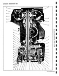 |
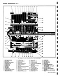
39 38 37 36 Fig 6E 1 Corvair Powerglide Cross Sectional View |
|
 |
39 Removing Element from Support CAUTION Never shake swing or wring the element to remove excess oil or solvent This may rip or tear the polyurethane material of the element Instead always SQUEEZE the excess |
|
 |
starter assembly forward to clear housing and remove starter Disassembly Refer to Figures 8 38 and 8 39 1 Disconnect the field coil connectors from the motor solenoid terminal 2 Remove through bolts 3 Remove |
|
 |
Page Corvair 500 700 and 900 Series 8 1 Engine Electrical 8 1 Wiring Diagrams 8 39 Chassis Electrical 8 46 ENGINE CORVAIR 500 71 II Page General Trouble Shooting 8 2 Battery |
|
 |
Shaft Rear Oil Seal 52 Clutch Drum Hub 38 Pinion Shaft Bushing 53 Clutch Drum Selective Thrust 39 Rear Pump Wear Plate Washer 40 Reverse Piston Outer Seal 54 Clutch Drum Bushing 41 Planet Carrier |
|
 |
Piston Cushion 37 Turbine Shaft Rear Bushing Spring Seat 38 Converter Assembly 53 Low Servo Piston Shaft 39 Converter Hub Bushing 54 Relief Ball Spring Retainer 40 Rear Pump and Reverse Piston 55 Low Servo |
|
 |
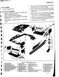
Cover Rear Seat Support Heater Opening 38 Plate Engine G 18 Support Rear Seat Center 39 Panel Rear Quc 19 Cover Rear Seat Pan Duct Wheelhouse Le 20 Extensions Rear Seat Front Pan Rear |
|
 |
GEAR A w t REAR BEARING 1 RETAINER k I st GEAR q W Fig 6D 39 tomoving 1 2 Synchronizer and First Goof Sleeve from Mainshaft INSPECTION AND REPAIR Wash the transmission case inside |
|
 |
Oear Rearing 37 1 2 Synchronizer Hub 49 Clutch Gear Bearing Selective 38 Synchronizer Key Snap Ring 39 Reverse Shifter Head 50 Snap Ring Clutch Shaft bottoming 40 1 2 Shift Fork stop |
|
 |
Drain Plug 17 Seal Ring 38 Pinion Shaft Se 18 Converter Hub Seal Auto Trans only 39 Pinion Auto T 19 Stator Shaft Auto Trans only Drive Gear y r Fig 6C 20 Measuring Gauge |
|
 |
left rear shroud in place Install new oil cooler seals in oil cooler adapter fig 6A 107 39 Install oil cooler retaining bolt and flat washer using anti seize compound on threads and torque |
|
 |
piston is r moved from cylinder A cylinder mounted r Ige reamer is available at local jobbers 39 1 emove ridge and or deposits from cylinder bore i hile holding cylinder with studs or bolts |
|
 |
Pistons Rings and Cylinder Assembly 6A 38 Cylinders 6A 38 Piston Rings 6A 39 Piston and Connecting Rod Assembly 6A 40 Engine Rear Housing 6A 40 Oil Pump 6A 40 Rear Housing Seal |
|
 |
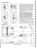
Cage Nut Repair 3 19 Troubles and Remedies 3 36 Specifications 3 38 Special Tools 3 39 DESCRIPTION cross member Cornering sway is controlled by rubber bushed control arms The rear suspension is independently sprung |
|
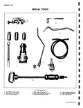 |
SPECIAI 4 7 9 Fig 5 39 l J 8113 KMO 3A Tubing Cutter 4 J 8051 Double 2 J 7647 Bleeder Valve Wrench 5 J 8049 KMO 3 J 8363 Brake Adjusting Toot |
|
 |
39 92 4 Reverse the lock cylinders so that the head of the cylinder is now toward you Insert the spring retainer so that one of its six prongs enters into each of the springs |
|
 |
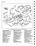
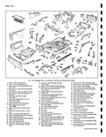
39 44 1 1 55 53 5 40 41 43 45 42 50 48 54 52 56 49 46 57 47 58 o o P 59 Pow rglide Exploded View CORVAIR SHOP MANUAL |