| Book |
Page |
Context |
 |
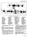 |
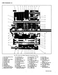
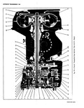
39 j 34 33 T i 1 O n 1 0 P91 To 14 7 1 W 51 48 47 46 45 44 43 42 38 37 Fig 39 Six Cylinder C 1 Shaft ...
Compressor Rear Head Bearing Pack 50 High Pressure Relief 38 Rear Cylinder Half Valve and O Ring 39 Oil Inlet Tube 51 Rear Head to Shell O Ring Retaining Nuts 40 Oil Inlet Tube |
|
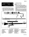 |
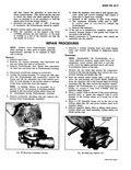
39 I 37 38 14 40 4142 43 1 f Telescoping Mast Jacket 23 Directional Lever 34 Directional Wiring Cover 24 Directional Wiring Connectors 35 Directional Wiring Clamp 25 Upper Snap Ring 36 Screw ...
Steering Shaft Assembly 37 Lower Snap Ring 27 Damper Spring 38 Lower Bearing 28 Damper Washer 39 Screws 29 Directional Housing 40 Lower Bearing Retainer 30 Inner Mast Jacket 41 Felt Sea 31 Stop Bolt |
|
 |
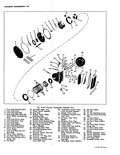
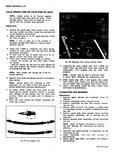
bore I a Fig 7E 38 Clutch Flange and Low Sun Gear Retainer Ring Installation Fig 7E 39 Installing Front Pump Shaft Thrust Washer Drive Hub Snap Ring 2 Install new bushing as illustrated ...
Repoin i If bronze thrust washer drive hub is worn remove the top snap ring fig 7E 39 and replace it Rear Pomp and Reverse Piston Assembly Disassembly NOTE All number references in this procedure |
|
 |
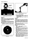
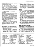
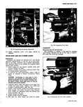
first remove valve assembly b Manually operate pump clockwise to release pump from lock out position fig 39 c told bellows plunger arm from moving then push in against bottom of bellows with thumb ...
base 9 To akssemble washer unit reverse above procedures HOLDING CONTACTS OPEN RAMP TANG PLUNGER ARM Fig 39 Releasing Pump from Lockout Position i5 ASSEMBLIES Temperature indicator lamp gauge and warning buzzer are conilected |
|
 |
39 38 37 36 35 ission Croso Sectional View 28 Reversel Shifter Head Shaft 42 Shift Finger 29 Interlock Pin 43 Special Snap Ring 30 1 2 Shift Fork Shaft 44 Shifter Shaft Seal ...
Gear Bearing 37 1 2 Sy chronizer Hub 49 Clutch Gear Bearing 38 ynchrdnizer Key Snap Ring 39 ReverseF Shifter Head 50 Snap Ring Input 40 1 2 Shift Fork Shaft Bottoming Stop |
|
 |
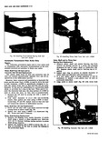
carburetor attaching nuts and remove carburetor from Turbocharger assembly i r r ev t 1 r Fig 39 Removing Compressor Housing b Push the impeller from side to side against indicator point and record readings ...
that secure the compressor housing to the bearing housing then remove the compressor housing and gasket fig 39 2 Hold the turbine wheel blades with a cloth and remove the self locking nut LEFT HAND |
|
 |
Bond 13 7 6 v 15 38 30 31 37 32 33 36 I34 35 o nrs 39 44 3 55 60 40 41 43 I 45 53 51 42 t f 01bl ...
Piston Cushion 37 Turbine Shaft Rear Bushing Spring Seat 38 Convherter Assembly 53 Low Servo Piston Shaft 39 Con lerter Hub Bushing 55 Low Servo Piston Return 40 Rear Pump and Reverse spring Pistojn Assembly |
|
 |
Rear Selective Thrust Washer 52 Clutch Drum Hub 38 Pinion Shaft Bushing 53 Clutch Drum Selective Thrust 39 Rear Pump Wear Plate Washer 40 Reverse Piston Outer Seal 54 Clutch Drum Bushing 41 Planet Carrier |
|
 |
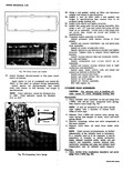
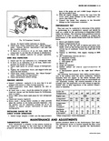
PLASTIC HOSE Fig 39 Connecting Rod Bearing Replacement 10 Install crankcase cover and upper shroud as outlined PISTON RING AND OR CYLINDER GASKET Replacement Cylinders and pistons are serviced as a unit and the operation |
|
 |
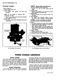
Using a new gasket install oil filter and Delcotron adapter and torque to specifications 39 Install a new oil filter with a new gasket and tor ue to specifications then connect wire to oil pressure |
|
 |
plastic or rubber hose on connecting rod bolt to protect crankshaft journals fig 39 5 Remove spark plug from cylinder being serviced and position connecting rod so bearing may be removed 6 Remove bearing from |
|
 |
Drive out old seal with a pin punch inserted thro Ih access holes in stator shaft fig 39 2 Install new seal using J 8448 1 as illustrated fig 40 Press seal until it bottoms |
|
 |
SIMOWMEME C r i y 1 41 40 39 |
|
 |
Compressor Suction Pressure 10 11 13 14 17 19 Discharge Air Temp at 34 36 38 38 39 40 R H Outlet 40 41 43 43 44 45 When compressor clutch disengages kND ADJUSTMENTS suction |
|
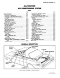 |
Idle Adjustment I5 37 Operating Instructions 15 37 Air Conditioning Control Panel 15 37 Special Tools 15 39 DESCRIPTION DASH DIFFUSER OUTLETS CONDENSER RECEIVER DEHYDRATOR r ther Air Conditioning System CORVARt SHOP MANUAL |
|
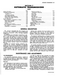 |
pint ION 7 RANSMISSIONS IDEX Page Inspection and Repair of Transmission Components 7 39 Front Pump 7 40 Clutch Drum 7 41 Turbine Shaft 7 46 Pump Shaft 46 Rear Pump and Reverse Piston Assembly |