Jeep Parts Wiki | Ford Parts Wiki
Home | Search | Browse
|
Body Service Manual August 1964 |
|
Prev
 Next
Next
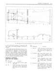
4A 2 GENERAL INFORMATION and if necessary realigned in or Ier to aeqtnqimly inches further from the tram bar than the pointer cstablish proper dimensions There are many used at the rearward location With the proper classifications of tools that may be employed to settings the tram bar will be on a plane parallel Correct the average collision damage situation to that of the body plane The exception to this including frame straightening machines lighter would be when one of the reference locations is external pulling equipment and standard body jacks included in the misaligned area then the parallel nlane between the bod and the tram bar HIBV nat To assist in checking alignment of the underbody I F 4 I comionents re riiring minor underbodydanriace or PYQVLUL AHH wmplemm O1 the lEDlu5 mg 1 I l D V D E tram gage should be set at the specified dimen locating replacement parts the following underbodv Q 7 sion to check the accuracy of the repair dimensions and alignment checking information is o operation presented BQDY TRAM GAGE CAR PREPARATION I fl M tI l in t N u1m 9 TtEt1 f isc tu u iPK 1g n fn Preparing the car for the underbody alignment ui ma 2 1 Y I IE um E1 M U IZ 1 1 g k check involves the following The tram gage required to perform all recom r I k rc li ust be unable S S P I I it 1 ence me eat on ievei Stance of extending to a length oi 91 At least one oi the 2 t l c t is at be c iable of a maximum VU ul pUu1 I muh if 2 The weight of the car should be supported at reach ot 17 L the wheel locations Horizontal dimensions shown in the upper portion of Figures 4A2 and 4A5 are calculated on a plane 3 A visual damage inspection should be made parallel to the plane of the underbody Precision to eliminate needless measuring Obviously dam measurements can be made only if the tram is aged or misaligned areas can often be located by properly adjusted so as to remain parallel to the sight plane of the underbody during measuring operations TRAMMING SEQUENCE A proper tramming tool is essential for analyzing o The tramming sequence will vary depending upon and determining the extent ot collision misalign r r the nature and location of the misaligned area ment present in underbody construction Prior to ierforming an trammirr oi wt pnnncnptzs or TRAMMING I o I gi I the accuracy or reference points to be used must In the upper portion of 4A2 and 4A5 all reference be determined A measurement that originates locations shown are symmetrical about the center from a reference point which is included in a dam linc of the vehicle For example when performing aged area will produce untrue results and confuse a cross check of the body floor pan area dimension the evaluation of the underbody condition Unlike N should measure the same distance in both the conventional type of frame design the unitized diagonal directions of the cross check operation type of body construction seldom develops the con Cross checking operations are used to determine dition of diamond in the floor pan area as a re the relationship between two locations on the suit of front or rear end collisions Therefore underbody underbody alignment checking can usually originate To mgm me assure tm a ay between any f 0 t XQ M gm ge 1j fi j y jrlmtej two reference points on the underbody two specifi t Ll IFS wml wub fave wen lu fu lm Jie nl canons Bm Equu E d suitab e for measui mg one o ie undamagec sus pension locations should be used as a beginning a The horizontal dimension between the two f 1 nCE pcm If H ygpg Sjtugjjijyri Should exist PI IIIIIS mb IY3mm d where all of these locations are not suitable as b The vertical dimension from the datum line to reference Pgmtsv l II Olj mth IS Slwuld Dew the pmms 0 he u Hmm d AS an example the with the body floor pan area All other underbody diagonal measurement calculated on a horizontal colmlxmgnts Sh Id be 1is I I Ot Y sS1V 1Y from plane between reference points of dimension line this m i N shown in 4A5 is 78 25 32 inches The specifications from the datum line have a vertical UNDERBODY AUGNNIENT REFERENCE POINT height difference of 3 5 16 inches between the DIMENSIONS forward location of dimension N at vertical FIGURES 4A2 4A5 AND 4A8 dimension e and the rearward location of dimension N at vertical dimension h Dimensions to gage holes and other unthreaded The vertical pointer used at the forward location holes are measured to dead center of the holes should be positioned so as to extend 3 5 16 and flush to the adjacent surface metal Dimensions