Jeep Parts Wiki | Ford Parts Wiki
Home | Search | Browse
|
Body Service Manual August 1964 |
|
Prev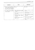
 Next
Next
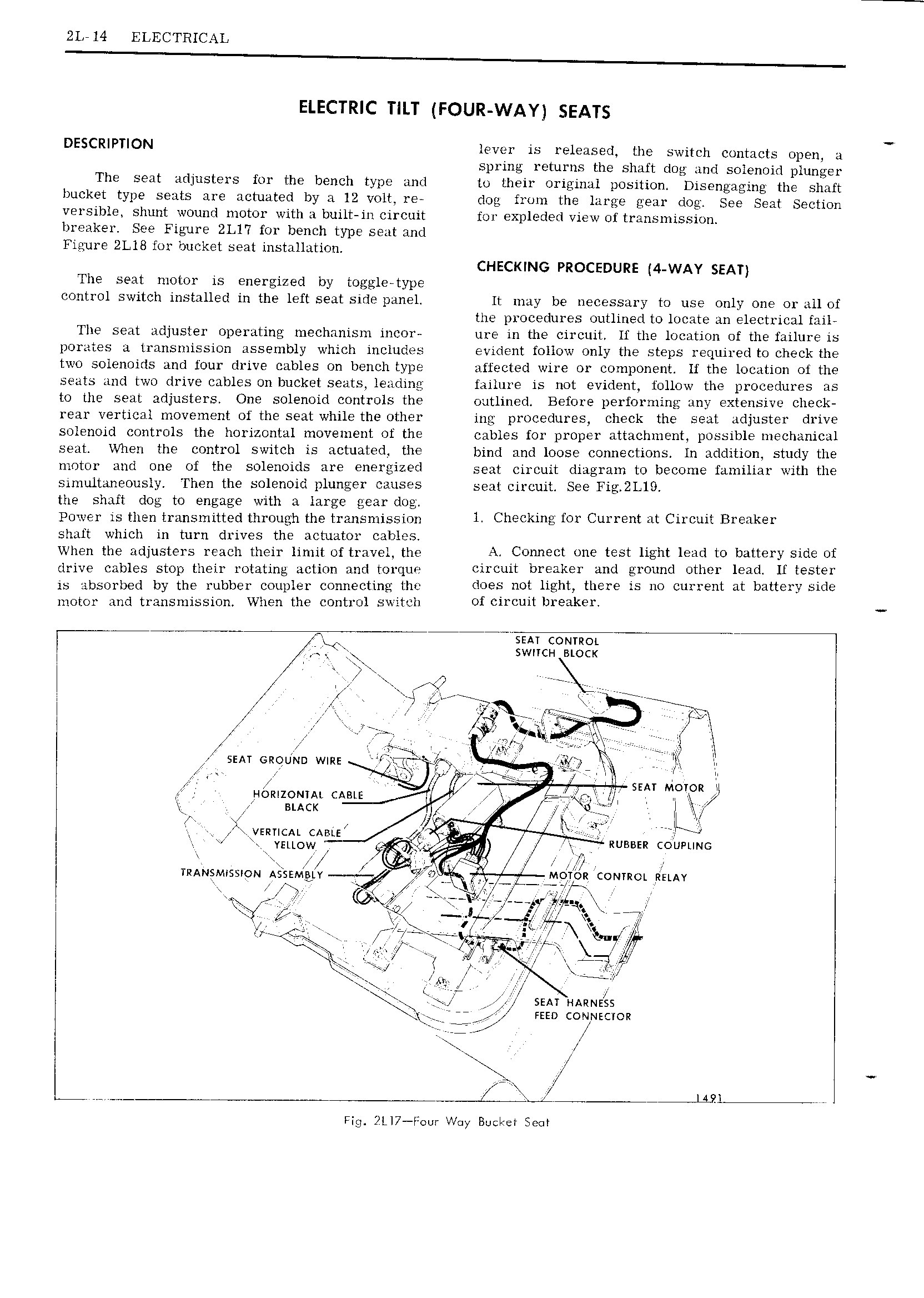
2L 14 ELECTRICAL ELECTRIC TILT FOUR WAY SEATS DESCRIPTION lever is released the switch contacts open a v spring returns the shaft dog and solenoid plunger The seat adjusters for the bench type and to their original position Disengaging the shaft bucket type seats are actuated by a 12 volt re dog from the large gear dog See Seat Section versible shunt wound motor with a built in circuit for expleded view of transmission breaker See Figure 2L1 7 for bench type seat and Figure 2Ll8 for bucket seat installation CHECKING PROCEDURE 4 WAY SEAT The seat motor is energized by toggle type control switch installed in the left seat side panel lt may be necessary to use only one or all of the procedures outlined to locate an electrical fail The seat adjuster operating mechanism incor ure in the circuit If the location of the failure is porgites a transmission assembly which includes evident follow only the steps required to check the two solcnoids and four drive cables on bench type affected wire or component lf the location of the seats and two drive cables on bucket seats leading failure is not evident follow the procedures as to the seat adjusters One solenoid controls the outlined Before performing any extensive check rear vertical movement of the seat while the other ing procedures check the seat adjuster drive solenoid controls the horizontal movement of the cables for proper attachment possible mechanical seat When the control switch is actuated the bind and loose connections ln addition study the motor and one of the solenoids are energizcd seat circuit diagram to become familiar with the simultaneously Then the solenoid plunger causes Sent circuit See Fig 2L19 the shaft dog to engage with a large gear dog Power is then transmitted through the transmission 1 Ch cking IOP C 1 1 Y Ht C11 0 11 BF k 1 shaft which in turn drives the actuator cables I When the adjusters reach their limit of travel the A Connect one test light lead to battery side ot drive cables stop their rotating action and torque Circuit breaker and ground other lead If tester is absorbed by the rubber coupler connecting the does 110t light HIGFG is HO C111 l Ht it b tt 1 Y side motor and transmission When the control switch of circuit breaker T i Y g swncu sioex iffi rI i I i s ee sneeeeeeeeeee I I I E eeeee ioooeeoe K 1 f I e r QL or Yi5 l V W r I as ii I L I VV7 V V rr J I SEAT GROUND wm I Q q Ig gggyi jp It I i r L W II J II I V I snr Moron II Homzomiu cggyl I F I IL I R suck I I Iz I ikj I We tt y IL vmnciu exim As I I YELLOW f Q I RUBBER COUPLING I p E l I an TRANSMISSION A EM IY wIW w 7 Moi z convict univ s t I ifi i 2 I ir r Hail RII fg 4 fi 7 iZ iiiioo is I I L I vet yt Q 77 y I I t iQg X s I I SEAT IIA zr 1s ss sg Faso common r w r Q Q 1 1 L Fig i L17 I w Way Buctcet seen