Jeep Parts Wiki | Ford Parts Wiki
Home | Search | Browse | Marketplace | Messages | FAQ | Guest
|
Body Service Manual August 1964 |
|
Prev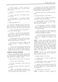
 Next
Next
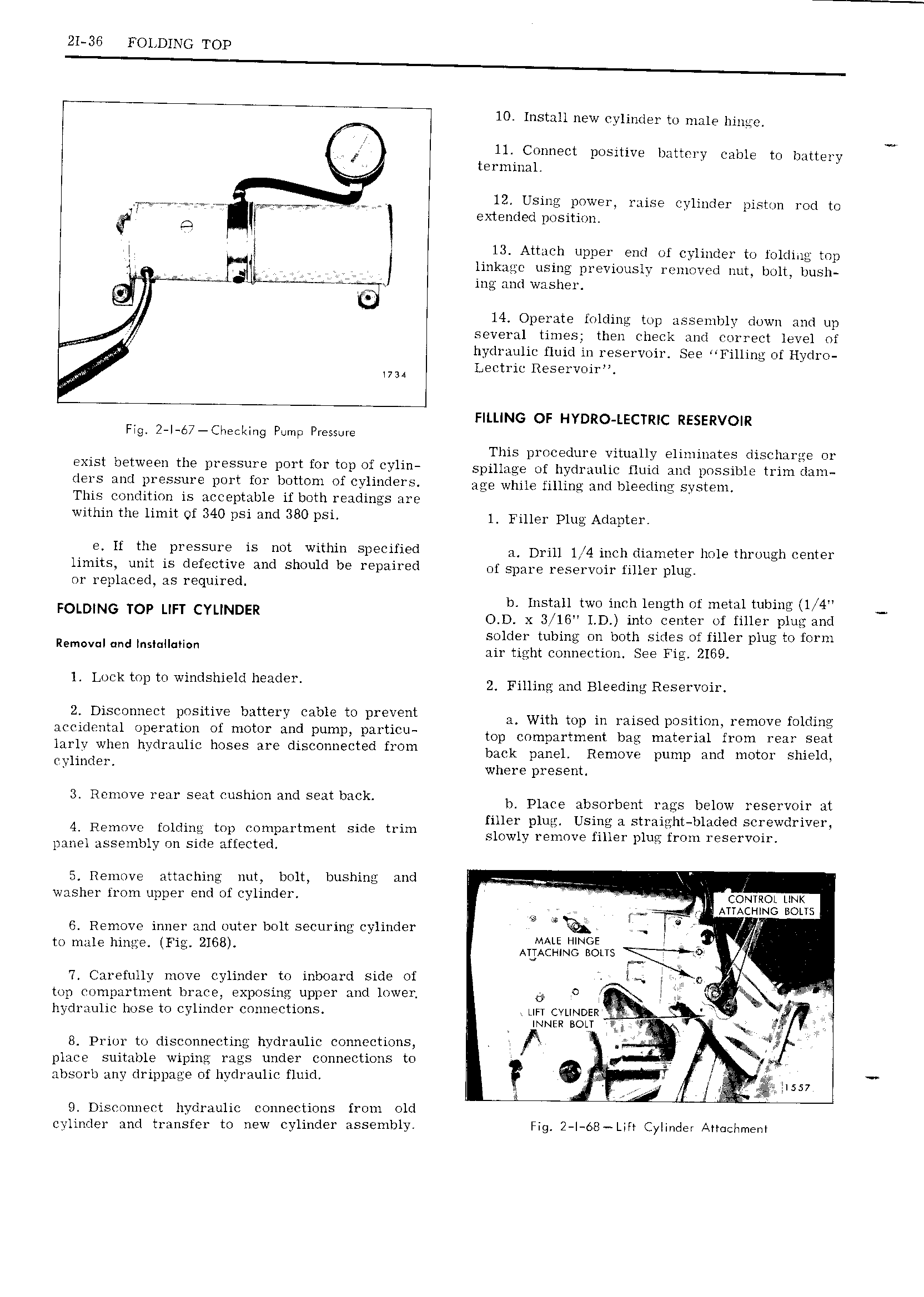
21 36 FOLDING TOP 10 Install new cylinder to male hinge 11 Connect positive battery cable to battery II terminal g 4 V 12 USUTQQ DOWEI TLTISG Cylinder piston rod to A li extended position is I i 13 Attach upper end of cylinder to folding top linkagc using previously removed nut bolt bush v L L T T ing and washer 4 lf A 14 Operate iolding top assembly down and up e several times then check and correct level of II We I hydraulic fluid in reservoir See Filling of Hydro II Lectric Reservoir we wa NI FILLING OF HYDRO LECTRIC RESERVOIR Fig 2 I 67 CIwecI Ing Pump Pressure This procedure vitually eliminates discharge or EXISI b lW9 l1 th PYESSUTQ DOTI f01 IOP IUI Y1i spillage of hydraulic fluid and possible trim dam I S wl l 1 5S 1 DUTY OY IMIIOHI of YU I age while filling and bleeding system This condition is acceptable if both readings are within the limit of 340 psi and 380 psi L Fjllggy plug Adaptgly 9 if the Pl SSu1 is DOI Within SIIECIHQG a Drill 1 4 inch diameter hole through center limits unit is defective and should be repaired ni Spare reservoir filler plug or replaced as required b Install two inch length of metal tubing 1 i I4 FOLDING TOP LIFT CYLINDER O D x 3 Il5 1 D into center of filler plug and solder tubing on both sides of filler plug to form II I v I IId I sI II II air tight connection See 2169 l Lock top to windshield header Z Filling and Bleeding R S9l vOh 2 Disconnect positive battery cable to prevent with mp in raised position remove Owing accidental operation of motor and pump parI icu Op Compnrtm m bag umtgrml hum rem Sm larlviwhen hydraulic hoses are disconnected from back panel Remove pump and mgm Shield IYh II where present 3 Remove rear seat cushion and seat back bl Place abSO1 b m rags bglmv reservoh at filler plug Using a straight bladed screwdriver 4 Remove folding top compartment side trim qlmvlv removp fiu9 p1uD frOm 1 PS rvOh panel assembly on side affected I I 5 Remove attaching nut bolt bushing and I i I washer from upper end of Cylinder i CONTROL LINK ATTACHING BOLTS eb S 5 c 6 Remove inner and outer bolt securing cylinder 9A v to male hinge Fig 2168 Arim2I INIgN LT ith 7 Carefully move cylinder to inboard Side Oi e top compartment brace exposing upper and lower G 0 A tkxvp hydraulic hose to cylinder connections uri cvuNt zR I I i V INNER BOLT f R if 8 Prior to disconnecting hydraulic connections in p EW I place suitable wiping rags under connections to v T 4 absorb any drippage of hydraulic fluid I g I f j ISS v Q ir Q Disconnect hydraulic connections from old cylinder and transfer to new cylinder assembly Fig 2 I 68 Lifr Cylinder Attachment