Jeep Parts Wiki | Ford Parts Wiki
Home | Search | Browse
|
Body Service Manual August 1964 |
|
Prev
 Next
Next
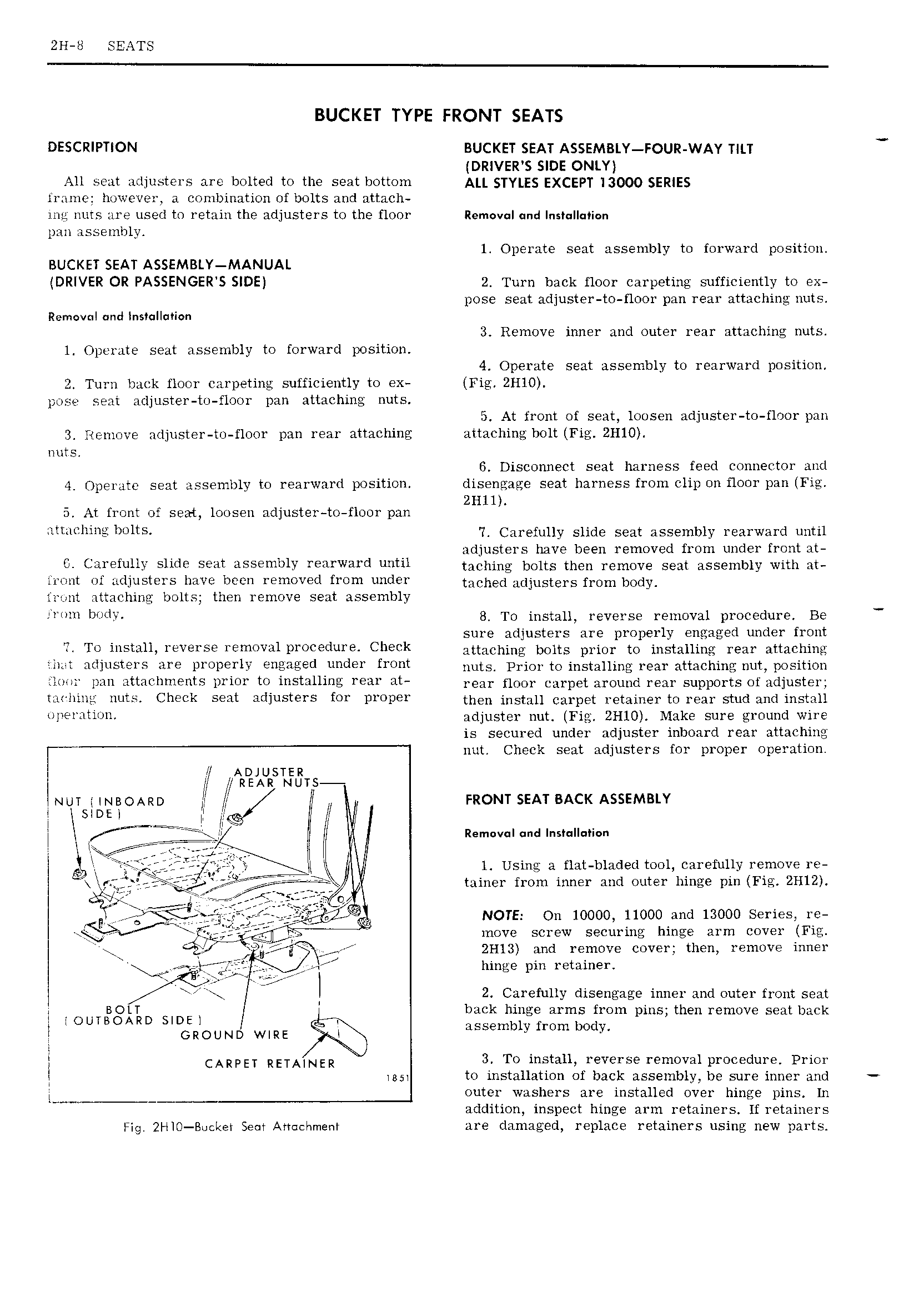
ZH 8 SEATS BUCKET TYPE FRONT SEATS DESCRIPTION BUCKET SEAT ASSEMBLY FOUR WAY TILT DRIVER S SIDE ONLY All seat adjusters are bolted to the seat bottom A 5 Y E EXCEPT 13000 SERIES frame however a combination of bolts and attach ing nuts are used to retain the adjusters to the floor Removal und nsI II i n pan assembly l Operate seat assembly to forward position BUCKET SEAT ASSEMBLY MANUAL DRIVER OR PASSENGER S SIDE 2 Turn back floor carpeting sufficiently to ex pose seat adjuster to floor pan rear attaching nuts Removnl and Insfulluvion 3 Remove inner and outer rear attaching nuts 1 Operate seat assembly to forward position 4 Operate seat assembly to rearward position 2 Turn back floor carpeting sufficiently to ex Fig 2Hl0 pose seat adjuster to floor pan attaching nuts 5 At front of seat loosen adjuster to floor pan 3 Remove adjuster to floor pan rear attaching attaching bolt Fig 2H10 nuts 6 Disconnect seat harness feed connector and 4 Operate seat assembly to rearward position disengage seat harness from clip on floor pan Fig 2H1l 5 At front of seat loosen adjuster to floor pan lml Ili l mus 7 Carefully slide seat assembly rearward until adjusters have been removed from under front at 6 Carefully Slide Sent assembly rearwvd fi1 taching bolts then remove seat assembly with et aront of adjusters have been removed from under mChEd djuSTe1 S f1 OmbOdy front attaching bolts then remove seat assembly l l I r rITv 8 To install reverse removal procedure Be sure adjusters are properly engaged under front T Te illsmuy l V9I S 1 mOV I l l O d I E Clmk attaching bolts prior to installingb rear attaching IL Hdlllslws RYE lJ1 JI7 l IY QHEHEZQCI UUCIEY fr i t nuts Prior to installing rear attaching nut position loor pan attachments prior to installing rear at Year mor carpet around Tear Supports Of adjuster Y I I l m lS Cheek s 9 t Hdlusters fer P OP then install carpet retainer to rear stud and install l l illi J adjuster nut Fig 2H10 Make sure ground wire is secured under adjuster inboard rear attaching T nut Check seat adjusters for proper operation I 1 ADJUSTER jj 1 REAR NUTS l NUT lNBOARD N TII 1 TI T FRONT SEAT BACK ASSEMBLY SIDE ll 1 I fg T T TT nemeven end nn5 1 I I I r rii1Q LTtj i Ij l 1 Using a flat bladed tool carefully remove re 1 1 i r at so 5T t e T T iiJi r 2e s ii r 1 tainer from inner and outer hinge pin Fig 2H12 ag z T i 9 Q eer g NOTE On 10000 11000 and 13000 Series re V move screw securing hinge arm cover Fig f j 4 2Hl3 and remove cover then remove inner r ew l r ev hinge pin retainer i x I 2 Carefully disengage inner and outer front seat i BOLT back hinge arms from pins then remove seat back l jOUTBOARD SIDE g 1 T GROUND WIRE assembly from body T CARPET RETAINER 3 To install reverse removal procedure Prior www to installation of back assembly be sure inner and Lww outer washers are installed over hinge pins In addition inspect hinge arm retainers If retainers Fig 2HlO Boeker Seat Armehmenr are damaged replace retainers using new parts