Jeep Parts Wiki | Ford Parts Wiki
Home | Search | Browse
|
Body Service Manual August 1964 |
|
Prev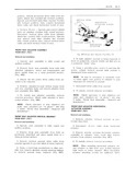

 Next
Next
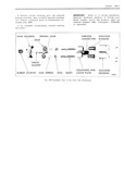
ZH 6 SEATS should be no free motion between upper and lower 3 Remove screws securing motor and trans channels Readjust Actuator Nas required until yujggirjn Support O gmt bmtmm h ml Fig 2H All free motion between channels has been re moved Check operation of seat d ljLlST l S and 4 Remove motor to motor support attaching make sure riCljllSt l S are in phase See step screws and remove motor assembly from support 5 under Front Seat Assembly Removal and installation 5 To install reverse removal procedure making sure rubber coupler is properly engaged at both FRONT SEAT ADJUSTER JACKSCREW motor and tizmsmission ends FOUR WAY TILT Removal and Installation FRONT SEAT ADJUSTER HORIZONTAL AND l Remove 1 ljl1S 3I vertical gearnut as pre VERTICAL CABLES FOUR WAY TILT viously described Removal nd Installation 2 Remove seat adjuster to seat bottom frame front and rear attaching bolts on side affected Fig l Remove front seat assembly from body with ZHG attached adjusters motor and transmission and place upside down on a clean protected surface As a bench operation remove jackscrew to adjuster linkage attaching rivet and remove jack 2 Detach both horizontal and vertical cables screw from adjuster tiSS llll lY Fic 2H8 from seat adjuster NOTE It may be necessary to manually raise 3 Remove screws securing horizontal and ver or lower upper rear portion of adjuster to gain tical cable end plate on side of transmission from access to jackscrew attaching rivet which cables are being removed and remove cables from seat assembly Fig ZH4 4 To install reverse removal procedure Check operation of scat adjusters and make sure ad 4 Disengage cable to be replaced from end plate justers are Nin phase See step 5 under Fl 0l IIT Seat Assembly Removal and Installation 5 To install cables reverse removal procedure FRONT SEAT ADJUSTER ELECTRIC MOTOR Removal d Insrulluiion FRONT SEAT ADJUSTER TRANSMISSION FOUR WAY TILT l Remove front seat assembly as previously described and place upside down on a clean pro Removal ma lnstqllgtiqn tt cted surface Fig ZH6 1 Remove front seat assembly from body with 2 Disconnect wire harness from motor relay attached adjusters motor and transmission and assembly place upside down on a clean protected surface 2 Disconnect wire harness connector from I CI CREW transmission Fig ZH4 RI U VERTICAL GEAR NUT 3 Remove screws securing horizontal and ver JACKSCREW tical cable end plate on both sides of transmission X and detach cables from transmission Q j I 4 Remove transmission to support attaching I w J bolts then disengage transmission from rubber 0 coupler and remove transmission from seat assembly rmi is 5 To install reverse removal procedure lm Disassembly and Assembly of Trunsmissicn l Remove front seat adjuster transmission from Fig 2H8 Fmni Seat Adjuster Foo May Tilt seat assembly