Jeep Parts Wiki | Ford Parts Wiki
Home | Search | Browse
|
Body Service Manual August 1964 |
|
Prev

 Next
Next
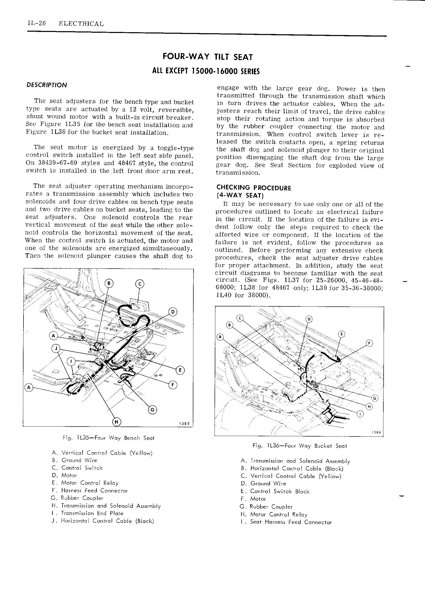
lL 26 ELECTRICAL FOUR WAY TILT SEAT All EXCEPT ISOOO l6000 SERIES DESCRIPTION engage with the lartre gear dog Power is then transmitted through the transmission shaft which The seat adjusters lor the bench type and bucket in turn drives the actuator cables Whcn the ad typc seats are actuated by a 12 v0lt reversible justers reach their limit of travel the drive cables shunt wound motor with a built in circuit breaker stop their rotating action and torque is absorbed See Figure lL35 for the bench seat installation and by the rubber coupler connecting the motor and Figure lL36 for the bucket scat installation transmission When c0ntr Jl switch lever is re leased the switch contatxts npen a sprint returns The sent 10l01 is iZ il by 3 li0 JE1 tYD the shaft det and solenoid plunger to their original control switch installed in the left seat side panel position disengaging the shaft dog from the large On 38439 67 69 styles and 48467 Style the COHtl Ol gear dog See Seat Section for exploded View of switch is installed in the left lront door arm rest transmission The seat adjuster operating mechanism incorpo CHECKING PROCEDURE rates a transmission assembly which includes two 4 WAY SEAT snlenuicls and four drive Cables 011 bei1Ch typ seats it may be necessary to use only One Or all nf the and twrr drive cables on bucket seats leadins t0 the pi or er1rn es outlined to locatc an electrical failure seat Mliusters One svlsrwid tr01S the Fear in the r n r uit it the ionation ofthe miiuro is evi vertical movement of the seat while the other sole dent fryllgyv Oniy the Stops i E qnii n i tn Check the noid controls the horizontal movement ofthe Seat affected wire or component H the location of the When the control switch is actuated the motor and failure is nrii vir1gnt fqiiirjiw the pi nqodiii s s one ol the solenoids are energized simultaneously niiiiinorr Boinyn pgyfnpining any extensive check Then the solenoid plunger causes the shaft dog to Dpnnnqtnyiss ghggk thi ggat yirijiistor drive cables for proper attachment ln addition study the seat silt l A circuit diagrams to become familiar with the seat lit t ircu it See Figs 1L3 7 for 25 28000 45 46 48 l Yl rtl B 68000 lL38 for 48467 only lL39 for 35 36 38000 TC Lra T lL40 for 38000 t e rigs l I 3 r V Tar Q ll3 l Cla ai TTY V gi sf73 isgj rrrr Lis rrrrr t i j in x jll at Ew F r i er r r r rrir lis r y sg ifi I c It y I t J 4 iirr 7 i i i 4 A g V i I y s l t r y lr A I I t i J tg fr rt F rye ra r r r GZ it I or F 4 5 A Y ir E i r iiiii l I rm I I 5 1 if Fig IL35 Four Way Benelr Sect Fzg lI 3o Fou Way Buoltot Soov A Vertiool Control Coble Yellow B Ground Wire A Transmission ond Solenoid Assembly C Control Switoli B Horizontol Control Coble Block D Motor C Vertical Control Coble Yellow E Motor Control Reloy D Ground ware F Harness Feed Connector E Control Switch Block G Rubber Coupler F Motor H Transmission and Solenoid Assembly G Rubber Coupler I Tronsrriission End Flute H Motor Control Reloy J Horizontal Control Coble Block I Sect Harness Feed Connector

 Next
Next