Jeep Parts Wiki | Ford Parts Wiki
Home | Search | Browse
|
Body Service Manual August 1964 |
|
Prev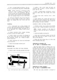
 Next
Next
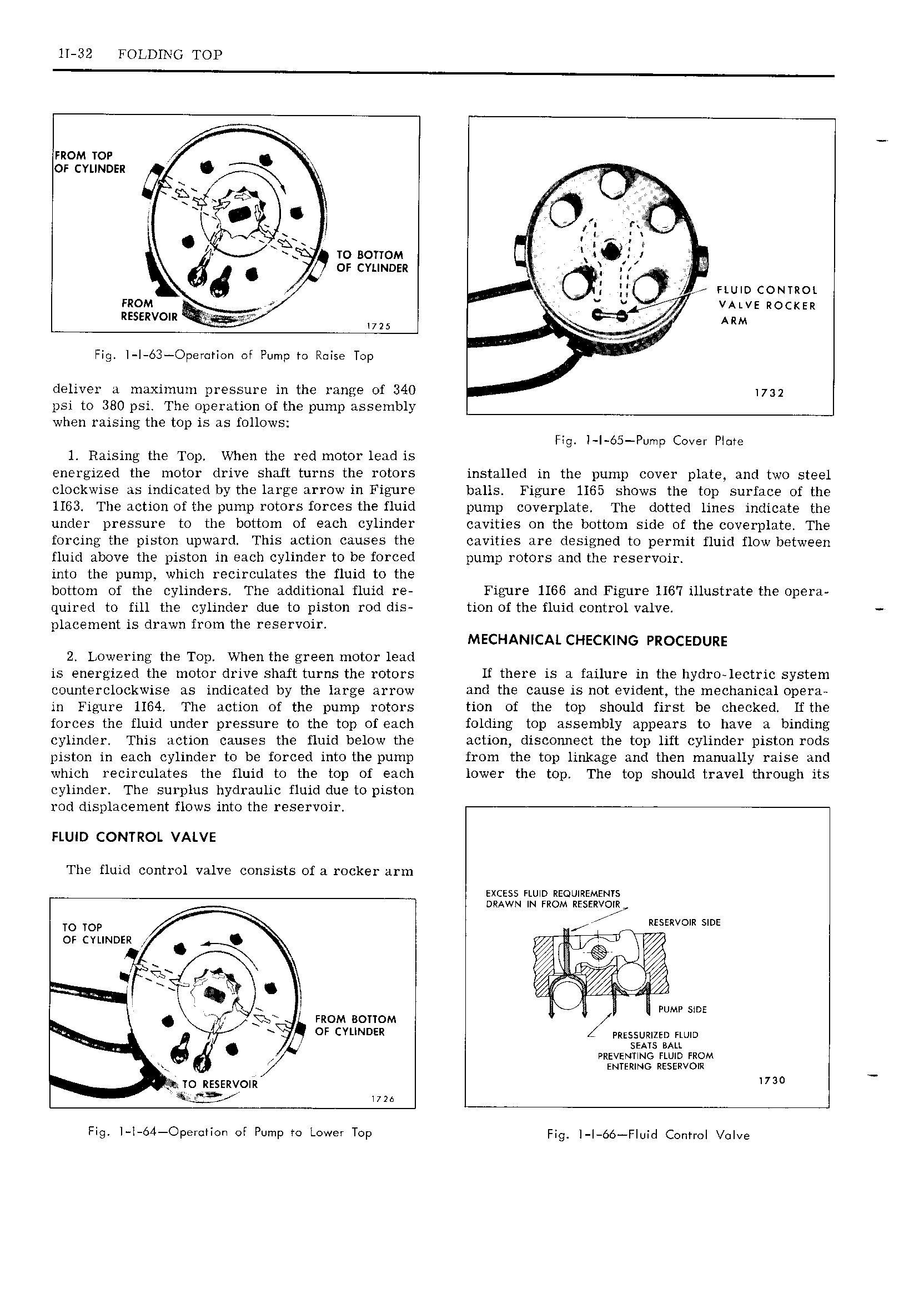
11 32 FOLDING TOP FROM mr OF cvuwnsn IA p gsgqg xgx x Pb 7 i I l f l 2 fx I x 9 to BOTYOM Ol7 4 OF CYLINDER K j B 6 P ll QZ F FLUID comkoi FROM J M V 7 VALVE R0cI EIz RESERVOIR ARM wu t FlQ l 63 Operoricn of Pump rg Raise Top i t a deliver a maximum pressure in the range of 340 173 psi to 380 psi The operation of the pump assembly when raising the top is as follows Fig I I 65 Pump Cover Plate 1 Raising the Top When the red motor lead is energized the motor drive shaft turns the rotors installed in the pump cover plate and two steel clockwise as indicated by the large arrow in Figure balls Figure 1165 shows the top surface of the 1163 The action of the pump rotors forces the fluid pump coverplate The dotted lines indicate the under pressure to the bottom of each cylinder cavities on the bottom side of the coverplate The forcing the piston upward This action causes the cavities are designed to permit fluid flow between fluid above the piston in each cylinder to be forced pump rotors and the reservoir into the pump which recirculates the fluid to the bottom of the cylinders The additional fluid re Figure 1166 and Figure 1167 illustrate the opera quired to fill the cylinder due to piston rod dis tion of the fluid control valve placement is drawn from the reservoir MECHANICAL CHECKING PROCEDURE 2 Lowering the Top When the green motor lead is energized the motor drive shaft turns the rotors If there is a failure in the hydro 1ectric system counterclockwise as indicated by the large arrow and the cause is not evident the mechanical opera in Figure 1164 The action of the pump rotors tion of the top should first be checked Ifthe forces the fluid under pressure to the top of each folding top assembly appears to have a binding cylinder This action causes the fluid below the action disconnect the top lift cylinder piston rods piston in each cylinder to be forced into the pump from the top linkage and then manually raise and which recirculates the fluid to the top of each lower the top The top should travel through its cylinder The SL11 1 lS hydraulic fluid due to piston rod displacement flows into the reservoir FLUID CONTROL VALVE The fluid control valve consists of a rocker arm excess num nzoumsmsms aAwN IN mom nsssnvorgr To TOP I rc Izsssxvom sms or CYLINDER Q 7 F U x a ll PUMP SIDE FROM Bottom K 7L fn OF CYLINDER 4 Pnsssumzsu FLUID N SEATS BALL L PREVENTING num mom I mmznee nsstnvom aio RESERVOIRI 3 wu Fig I I 64 Opet IIo of Pump rc Lower Top I g 1 66 F U I COHHOI VOIVE