Jeep Parts Wiki | Ford Parts Wiki
Home | Search | Browse
|
Body Service Manual August 1964 |
|
Prev
 Next
Next
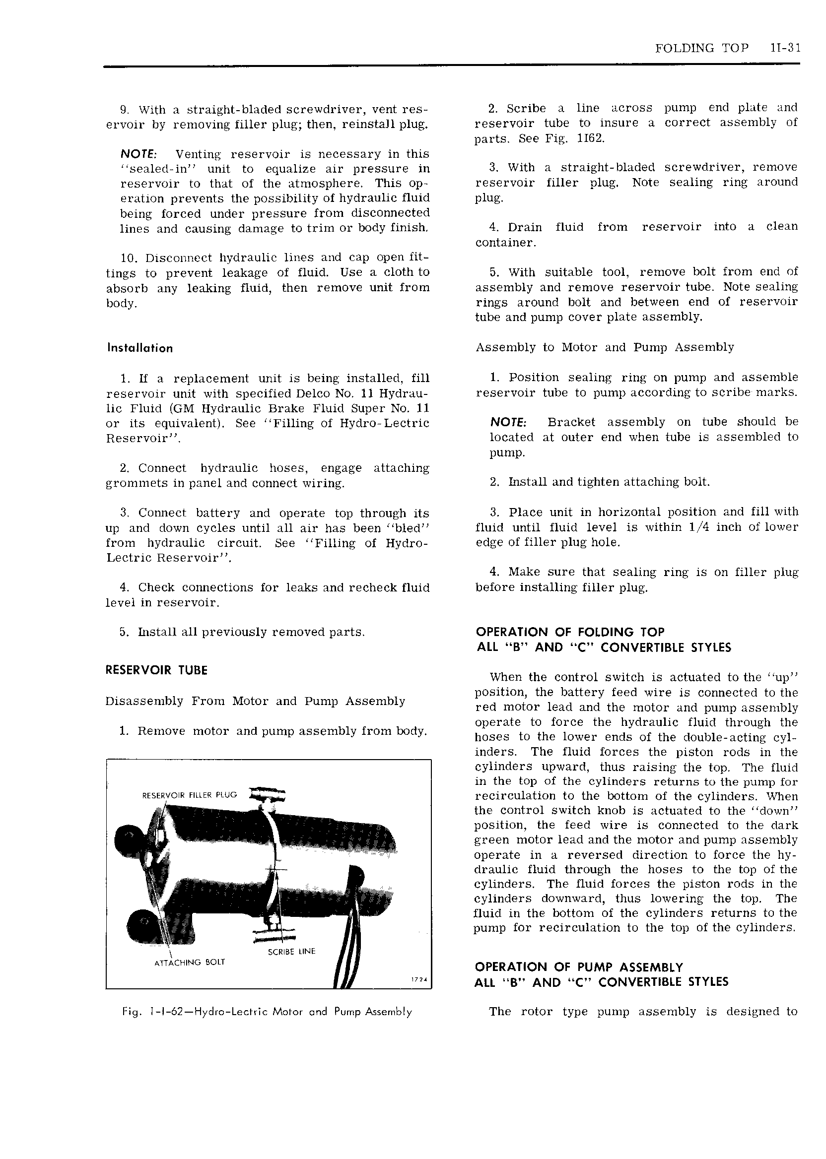
FOLDING TOP ll Bl 9 With a straight bladed screwdriver vent res 2 Scribe a line across pump end plate and ervoir by removing filler plug then reinstallplug reservoir tube to insure a correct assembly of parts See Fig 1162 NOTE Venting reservoir is necessary in this sealed in unit to equalize air pressure in 3 With a straight bladed screwdriver remove reservoir to that of the atmosphere This op reservoir filler plug Note sealing ring around eration prevents the possibility of hydraulic fluid plug being forced under pressure from disconnected lines and causing damage to trim or body finish 4 Drain fluid from reservoir into a clean container 10 Disconnect hydraulic lines and cap open fit tings to prevent leakage of fluid Use a cloth to 5 With suitable tool remove bolt from end of absorb any leaking fluid then remove unit from assembly and remove reservoir tube Note sealing body rings around bolt and between end of reservoir tube and pump cover plate assembly Installation Assembly to Motor and Pump Assembly 1 if a replacement unit is being installed fill 1 Position sealing ring on pump and assemble reservoir unit with specified Delco No 11 Hydrau reservoir tube to pump according to scribe marks lic Fluid GM Hydraulic Brake Fluid Super No 11 or its equivalent See Filling of Hydro Lectric NOTE Bracket assembly on tube should be Reservoir located at outer end when tube is assembled to pump 2 Connect hydraulic hoses engage attaching grommets in panel and connect wiring 2 IHSHH and tighi n attaching b0lt 3 Connect battery and operate top through its 3 Place unit in horizontal position and fill with up and down cycles until all air has been bled fluid until fluid level is within li 4 inch of lower from hydraulic circuit See Filling of Hydro edge of filler plug hole Lectric Reservoir 4 Make sure that sealing ring is on filler plug 4 Check connections for leaks and recheck fluid before installing filler plug level in reservoir 5 Install all previously removed parts OPERATION OF FOLDING TOP ALL B AND C CONVERTIBLE STYLES RESERVOIR TUBE When the control switch is actuated to the up V position the battery feed wire is connected to the D1 blY FT M t d P l Assmbly red motor me and me motor and pump assembly 1 Remove motor and pump assembly from body Eggggtetotihgoiciieihgnggdgfuikg G35 indersr The fluid forces the piston rods in the cylinders upward thus raising the top The fluid in the top of the cylinders returns to the pump for RESERYOIR FMR PLUG sym recirculation to the bottom of the cylinders When the control switch knob is actuated to the down W gl position the feed wire is connected to the dark green motor lead and the motor and pump assembly operate in a reversed direction to force the hy v draulic fluid through the hoses to the top of the V cylinders The fluid forces the piston rods in the t cylinders downward thus lowering the top The Il fluid in the bottom of the cylinders returns to the Z pump for recirculation to the top of the cylinders sense une A t A OPERATION or PUMP ASSEMBLY ALL B AND C CONVERTIBLE STYLES Fig I l 62 Hydr Leenic Motor qnd Pump Assembly The rotor type pump assembly is designed to