Jeep Parts Wiki | Ford Parts Wiki
Home | Search | Browse
Prev
 Next
Next
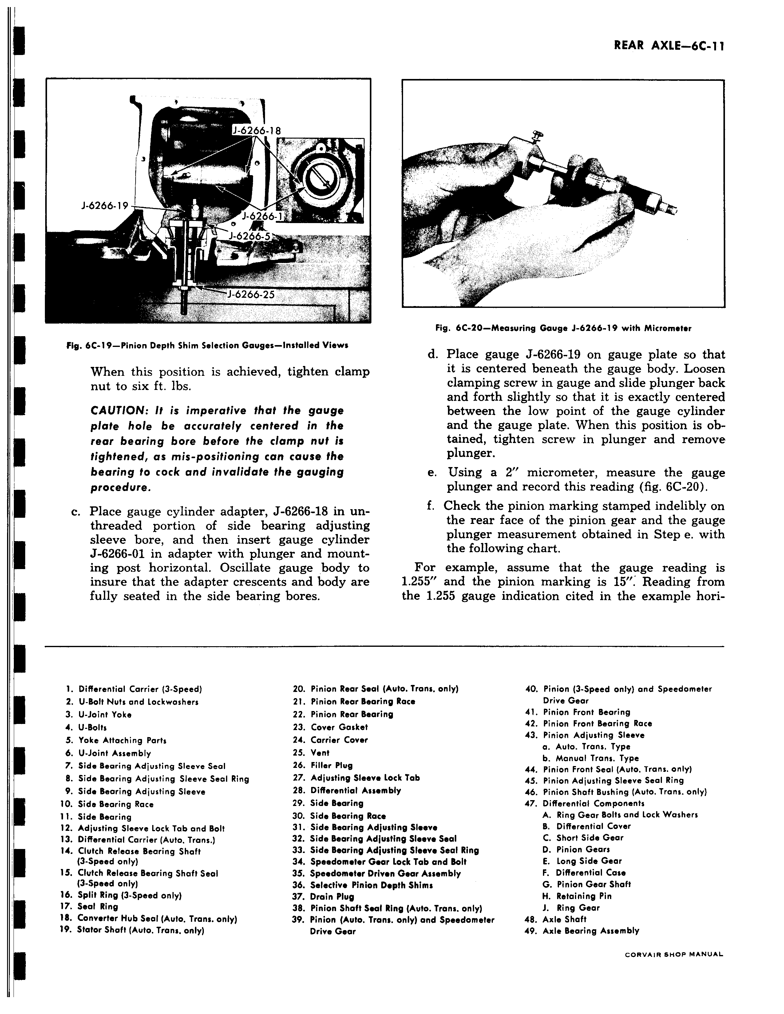
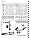
1 6266 18 J 6266 19 r J 6266 1 r J 6266 5 R J 6266 25 Fig 6C 19 Pinion Depth Shim Selection Gauges Installed Views When this position is achieved tighten clamp nut to six ft lbs CAUTION It is imperative that the gauge plate hole be accurately centered in the rear bearing bore before the clamp nut is tightened as mis positioning can cause the bearing to cock and invalidate the gauging procedure i c Place gauge cylinder adapter J 6266 18 in unthreaded portion of side bearing adjusting sleeve bore and then insert gauge cylinder J 6266 O1 in adapter with plunger and mounting post horizontal Oscillate gauge body to insure that the adapter crescents and body are fully seated in the side bearing bores 1 Differential Carrier 3 Speed 20 Pinion Rear Set 2 U Bolt Nuts and Lockwashers 21 Pinion Rear Set 3 U Joint Yoke 22 Pinion Rear Set 4 U Bolts 23 Cover Gasket S Yoke Attaching Parts 24 Carrier Cover 6 U Joint Assembly 25 Vent 7 Side Bearing Adjusting Sleeve Seal 26 Filler Plug 8 Side Bearing Adjusting Sleeve Seal Ring 27 Adjusting Slaw 9 Side Bearing Adjusting Sleeve 28 Differential Asi 10 Side Bearing Race 29 Side Bearing 11 Side Bearing 30 Side Bearing R4 12 Adjusting Sleeve Lock Tab and Bolt 31 Side Bearing A 13 Differential Carrier Auto Trans 32 Side Bearing A I 14 Clutch Release Bearing Shaft 33 Side Bearing A 3 Speed only 34 Speedometer C 15 Clutch Release Bearing Shaft Seal 35 Speedometer 0 3 Speed only 36 Selective Pinio 16 Split Ring 3 Speed only 37 Drain Plug 17 Seal Ring 38 Pinion Shaft Se 18 Converter Hub Seal Auto Trans only 39 Pinion Auto T 19 Stator Shaft Auto Trans only Drive Gear y r Fig 6C 20 Measuring Gauge J 6266 19 with Micrometer d Place gauge J 6266 19 on gauge plate so that it is centered beneath the gauge body Loosen clamping screw in gauge and slide plunger back and forth slightly so that it is exactly centered between the low point of the gauge cylinder and the gauge plate When this position is obtained tighten screw in plunger and remove plunger e Using a 2 micrometer measure the gauge plunger and record this reading fig 6C 20 f Check the pinion marking stamped indelibly on the rear face of the pinion gear and the gauge plunger measurement obtained in Step e with the following chart For example assume that the gauge reading is 1 255 and the pinion marking is 15 Reading from the 1 255 gauge indication cited in the example horiil Auto Trans only 40 Pinion 3 Speed only and Speedometer iring Race Drive Gear iring 41 Pinion Front Bearing 42 Pinion Front Bearing Race 43 Pinion Adjusting Sleeve a Auto Trans Type b Manual Trans Type 44 Pinion Front Seal Auto Trans only a Lock Tab 45 Pinion Adjusting Sleeve Seal Ring embly 46 Pinion Shaft Bushing Auto Trans only 47 Differential Components Ice A Ring Gear Bolts and Lock Washers diusfing Sleeve 8 Differential Cover Aiusting Sleeve Seal C Short Side Gear djusting Sleeve Seal Ring D Pinion Gears ear Lock Tab and Bolt E Long Side Gear riven Gear Assembly F Differential Case t Depth Shims G Pinion Gear Shaft H Retaining Pin at Ring Auto Trans only J Ring Gear ans only and Speedometer 48 Axle Shaft 49 Axle Bearing Assembly cnwv tw sF1OP MANUAL