Jeep Parts Wiki | Ford Parts Wiki
Home | Search | Browse | Marketplace | Messages | FAQ | Guest
|
Body Service Manual August 1964 |
|
Prev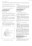

 Next
Next
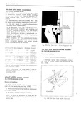
HEAR END LI 19 4 To install reverse removal pl l IIEClL 1 A M NU TAIL GATE LOCK ASSEMBLY E rlNG RIGHT OR LEFT SIDE I ALL STATION WAGON STYLES i M Removul und I s lI a n J xl I ll 1 Remove tail gate window assembly ESCUTCHEON IELECTRICI g SEMIm GAEKH 2 Remove tail gale window lower glass run 3 ij NUT channel on side from which lock is to be reinov I I 1 a 2 Iirs LI eff MII ll I Il T Remove screws 31 securing lock to tail gate 4 I IMI ll I V 4 It ll see Fig lF24 H RN 55 CONNECTOR 4 Move loek assembly to tail gate aecess hole clisengage remote rorl anti rattle clip and remove lock assembly mg m T II em Outside H iI Awt IIs TO S ev S 1 1r f TAIL GATE LOCK STRIKER NOTE On electrical styles disconnect wire ALL STATION WAGON STYLES harness from connector on escutcheun see 11 29 Removal und Installation 3 TO install reverse removal pmcgdurel i l Open tailrgate and with pencil mark position of striker on body pillar 2 Remove lock striker attaching screws anti TAIL GATE SUPPORT ASSEMBLY remove striker and adjusting plates from body ALL STATION WAGON STYLES pillar 3 To install tail gate lock striker place striker Removal and Installation and adjusting plates within marks on body pillar t s it L 1 Lower tail gate and support it in that position iggiojmst Lu D HMI Mmhuk Kalb bp hi 2 Remove screws securing support to tail gate and to body pillar and remove support see Figs I 11723 and lF24 A A 3 To install reverse removal procedure NOTE Ohjectionable slack in either support can lt r be corrected by rotating support platelsl at body i II se pillar STRIKER 5 I TAIL GATE WINDOW LOWER GLASS RUN CHANNEL gy l iI I QI A I RIGHT on LEFT sine AI Im It l x t I w 5 IIIL MI ALL STATION WAGON STYLES gr QI I Removal end I s II a x IM I I I il ADJUSTING PLATES I 1 Remove tail gate wrnrlow assembly 5 B I J 2 Remove bolts securing run channellsrl to tail Q QM SPACER gate see 11 24 W4 I view A 3 Force top of run channel rubber down into l tail gate and remove run channelts from tall gate through access hole Fig IF30 T Il Gene Locl Sntter A emI l