Jeep Parts Wiki | Ford Parts Wiki
Home | Search | Browse | Marketplace | Messages | FAQ | Guest
|
Body Service Manual August 1964 |
|
Prev
 Next
Next
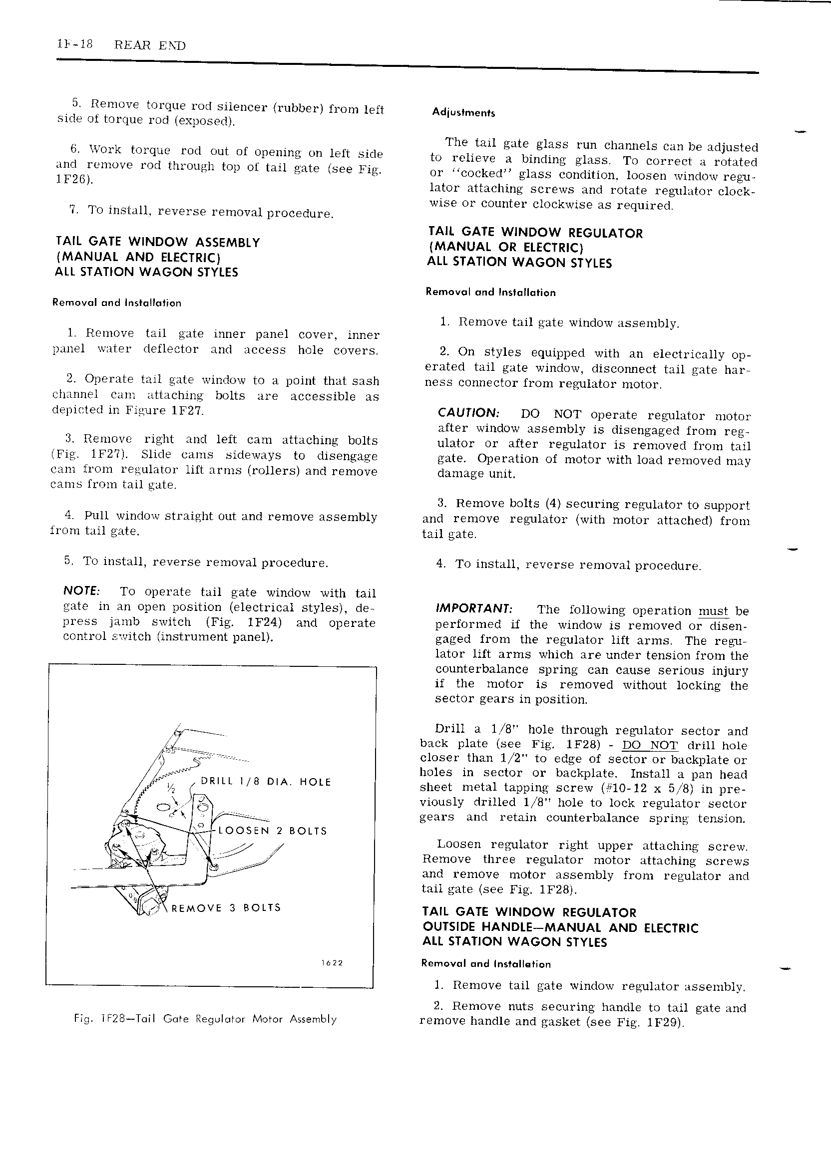
ll 11 REAR END 5 Remove torque rod silencer rubber from left Adjuslmenls side ol torque rod exposed V 7 I The tail gate glass run channels can be adjusted O llOYk I WCIOO wd OOI OI OPOUIOQZ OU left Sid to relieve a binding glass To correct a rotated JINI I mOV wi tIU OOt1Il wl Of Ulu EMP 569 Fil or cocked glass condition loosen window regu IFES lator attaching screws and rotate regulator clock wise or counter clockwise as required T To install reverse removal procedure TAIL GATE WINDOW REGULATOR TAIL GATE WINDOW ASSEMBLY MANUAL OR ELECTRIC MANUAL AND ELECTRIC ALL STATION WAGON STYLES ALL STATION WAGON STYLES Removal und Insl II Ii n Removal nd lnslqllmlun 1 Remove tail gate window assembly 1 Remove tail gate inner panel cover inner panel water deflector and access hole covers 2 On styles equipped with an electrically op erated tail gate window disconnect tail gate har 2 Operate tail gate window to a point that sash ness connector from regulator motor h innel cam attaching bolts are accessible as depicted in Figure 1F27 CAUTION DO NOT operate regulator motor after window assembly is disengaged from reg 3 Remove right and left cam attaching bolts ulgtgr Op after ggu1qtOy js removed mm gu Fi IFZIYL Slide 5ii l sideways to disengage gate Operation of motor with load removed may cam from regulator lift arms rollers and remove damage unit cams from tail gate 3 Remove bolts 4 securing regulator to support 4 Pull window straight out and remove assembly and remove regulator with motor attached from from tail gate tail gate 5 To install reverse removal procedure 4 To install reverse removal procedure NOTE To operate tail gate window with tail gate in an open position electrical styles de IMPORTANT The following operation must be press jamb switch Fig 1F24 and operate performed if the window is removed or disen control s itch instrument panel gaged from the regulator lift arms The regu lator lift arms which are under tension from the counterbalance spring can cause serious injury if the motor is removed without locking the sector gears in position Wi rrrr Drill a 1 8 hole through regulator sector and l back plate see Fig 1F28 DO NOT drill hole r r r c loser than 1 2 to edge of sector or backplate or I J t f holes in sector or backplate Install a pan head I Ni DRIII I II DIA HOLE sheet metal tapping screw 10 12 x 5 B in pre if A I viously drilled 1 8 hole to lock regulator sector gears and retain counterbalance spring tension r LLOOSEN 2 BOLTS M V 7 Loosen regulator right upper attaching screw 7 gi f Remove three regulator motor attaching screws rm LII 2 and remove motor assembly from regulator and tail gate see Fig 1F28 REMOVE 3 BOIIS TAIL GATE WINDOW REGULATOR OUTSIDE HANDLE MANUAL AND ELECTRIC ALL STATION WAGON STYLES waz Removul nd l sl ll li n 1 Remove tail gate window regulator assembly 2 Remove nuts securing handle to tail gate and Fig lF2S T iI Gore Regulmsr Mover Assembly remove handle and gasket see Fig lF29