Jeep Parts Wiki | Ford Parts Wiki
Home | Search | Browse
Prev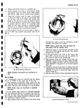
 Next
Next
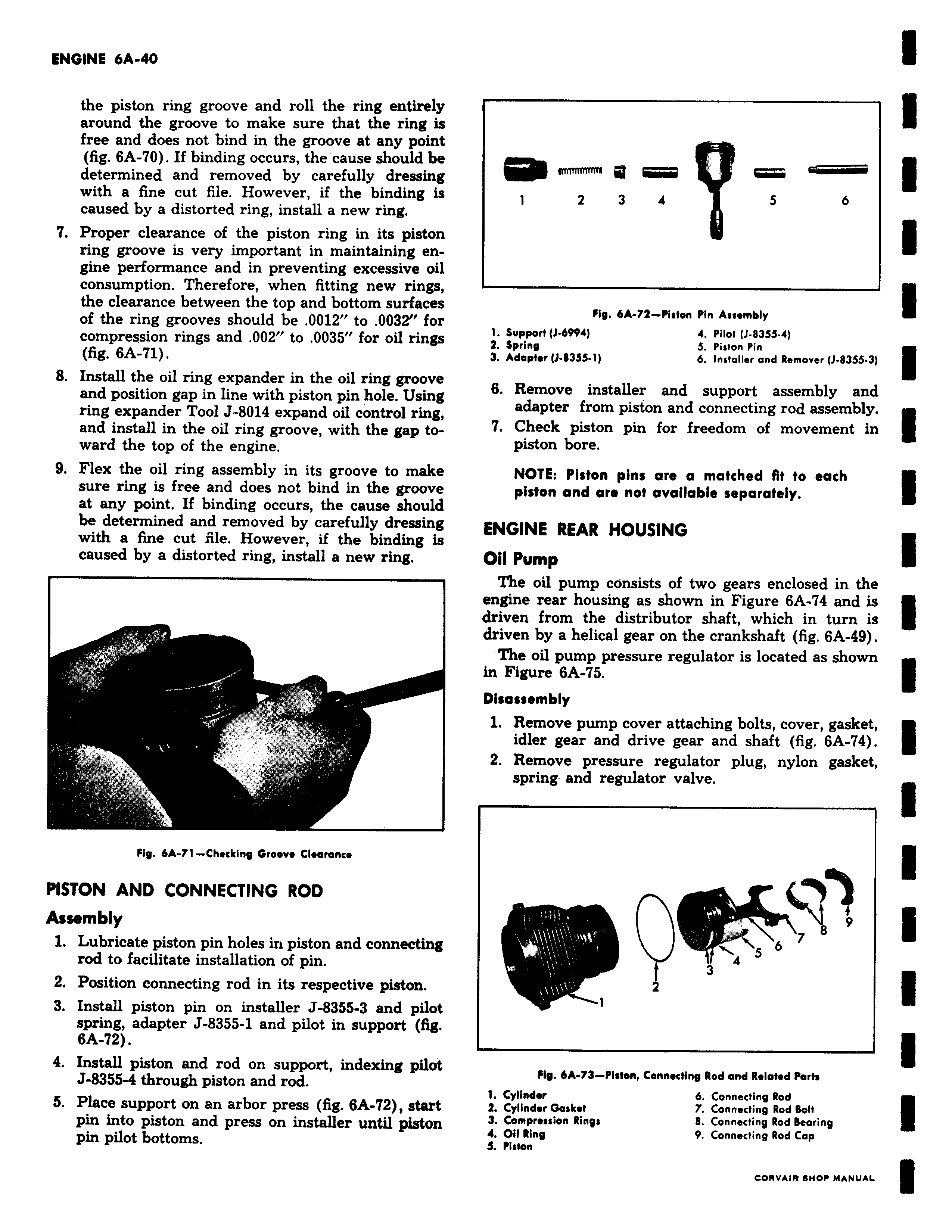
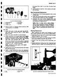
the piston ring groove and roll the ring entirely around the groove to make sure that the ring is free and does not bind in the groove at any point fig 6A 0 If binding occurs the cause should be determined and removed by carefully dressing with a fine cut file However if the binding is caused by a distorted ring install a new ring 7 Proper clearance of the piston ring in its piston ring groove is very important in maintaining engine performance and in preventing excessive oil consumption Therefore when fitting new rings the clearance between the top and bottom surfaces of the ring grooves should be 0012 to 0032 for compression rings and 002 to 0035 for oil rings fig 6A 71 8 Install the oil ring expander in the oil ring groove and position gap in line with piston pin hole Using ring expander Tool J 8014 expand oil control ring and install in the oil ring groove with the gap toward the top of the engine 9 Flex the oil ring assembly in its groove to make sure ring is free and does not bind in the groove at any point If binding occurs the cause should be determined and removed by carefully dressing with a fine cut file However if the binding is caused by a distorted ring install a new ring r Fig 6A 71 Checking Groove Clearance PISTON AND CONNECTING ROD Assembly 1 Lubricate piston pin holes in piston and connecting rod to facilitate installation of pin 2 Position connecting rod in its respective piston 3 Install piston pin on installer J 8355 3 and pilot spring adapter J 8355 1 and pilot in support fig 6A 72 4 Install piston and rod on support indexing pilot J 8355 4 through piston and rod 5 Place support on an arbor press fig 6A 2 start pin into piston and press on installer until piston pin pilot bottoms mrmmrm a 1 2 3 4 5 6 Fig 6A 74 Piston Pin Assembly 1 Support J 6994 4 Pilot J 83SS 4 Z Spring 5 Piston Pin 3 Adaptor J B3S5 1 6 Installer and Remover J 835S 3 6 Remove installer and support assembly and adapter from piston and connecting rod assembly 7 Check piston pin for freedom of movement in piston bore NOTE Piston pins are a matched fit to each piston and are not available separately ENGINE REAR HOUSING Oil Pump The oil pump consists of two gears enclosed in the engine rear housing as shown in Figure 6A 74 and is driven from the distributor shaft which in turn is driven by a helical gear on the crankshaft fig 6A 49 The oil pump pressure regulator is located as shown in Figure 6A 75 Disassembly 1 Remove pump cover attaching bolts cover gasket idler gear and drive gear and shaft fig 6A 74 2 Remove pressure regulator plug nylon gasket spring and regulator valve a 9 5 6 7 4 3 2 1 Fig 6A 73 Piston Connecting Rod and Related Parts 1 Cylinder 6 Connecting Rod 4 Cylinder Gasket 7 Connecting Rod Bolt 3 Compression Rings 8 Connecting Rod Bearing 4 Oil Ring 9 Connecting Rod Cap 3 Piston