Jeep Parts Wiki | Ford Parts Wiki
Home | Search | Browse
Prev
 Next
Next
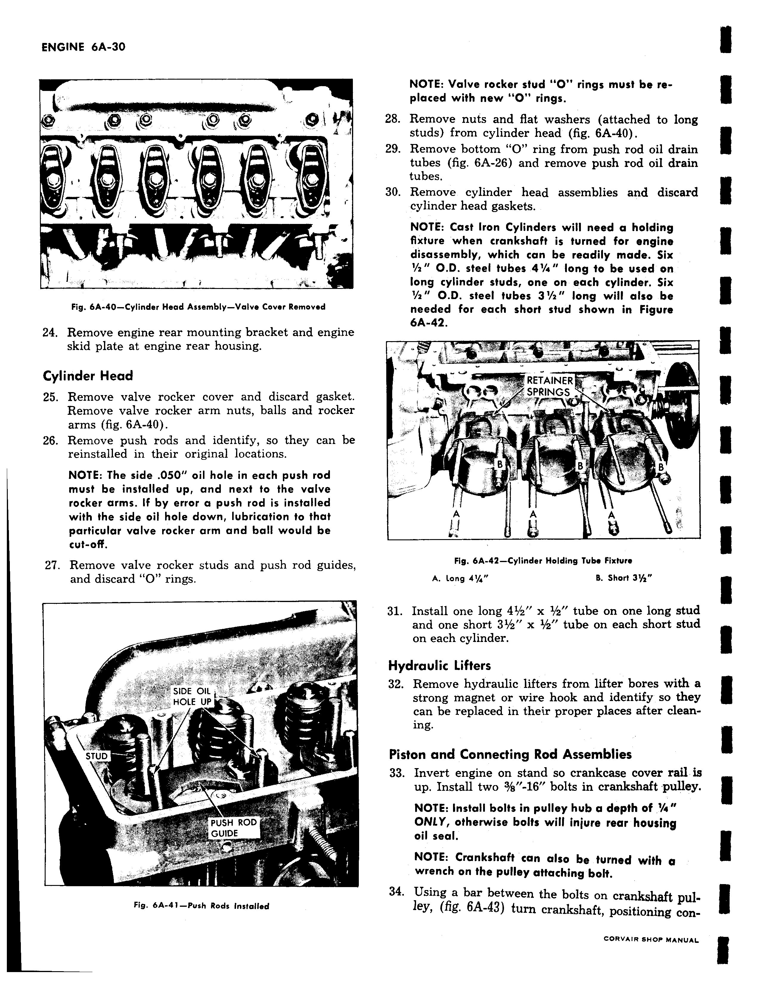
4 Al ow A A 1 d Fig 6A 40 Cylinder Head Assembly Valve Cover Removed 24 Remove engine rear mounting bracket and engine skid plate at engine rear housing Cylinder Head 25 Remove valve rocker cover and discard gasket Remove valve rocker arm nuts balls and rocker arms fig 6A 40 26 Remove push rods and identify so they can be reinstalled in their original locations NOTE The side 050 oil hole in each push rod must be installed up and next to the valve rocker arms If by error a push rod is installed with the side oil hole down lubrication to that particular valve rocker arm and ball would be cut off 27 Remove valve rocker studs and push rod guides and discard O rings ti S SIDE OIL HOLE UP y STUD PUSH ROD t ar GUIDE Fig 6A 41 Push Rods Installed NOTE Valve rocker stud O rings must be replaced with new O rings 28 Remove nuts and flat washers attached to long studs from cylinder head fig 6A 40 29 Remove bottom O ring from push rod oil drain tubes fig 6A 26 and remove push rod oil drain tubes 30 Remove cylinder head assemblies and discard cylinder head gaskets NOTE Cast Iron Cylinders will need a holding fixture when crankshaft is turned for engine disassembly which can be readily made Six 2 O D steel tubes 4 s long to be used on long cylinder studs one on each cylinder Six 2 O D steel tubes 3 s long will also be needed for each short stud shown in Figure 6A 42 RETAINER S SPRINGS r A A A Fig 6A 42 Cylinder Holding Tube Fixture A Long 41 4 B Short 3y 31 Install one long 41 z x 1 2 tube on one long stud and one short 31 2 x 1 z tube on each short stud on each cylinder Hydraulic Lifters 32 Remove hydraulic lifters from lifter bores with a strong magnet or wire hook and identify so they can be replaced in their proper places after cleaning Piston and Connecting Rod Assemblies 33 Invert engine on stand so crankcase cover rail is up Install two 3 a 16 bolts in crankshaft pulley NOTE Install bolts in pulley hub a depth of 4 ONLY otherwise bolts will injure rear housing oil sea NOTE Crankshaft can also be turned with a wrench on the pulley attaching bolt 34 Using a bar between the bolts on crankshaft pulley fig 6A 43 turn crankshaft positioning con