Jeep Parts Wiki | Ford Parts Wiki
Home | Search | Browse
Prev

 Next
Next
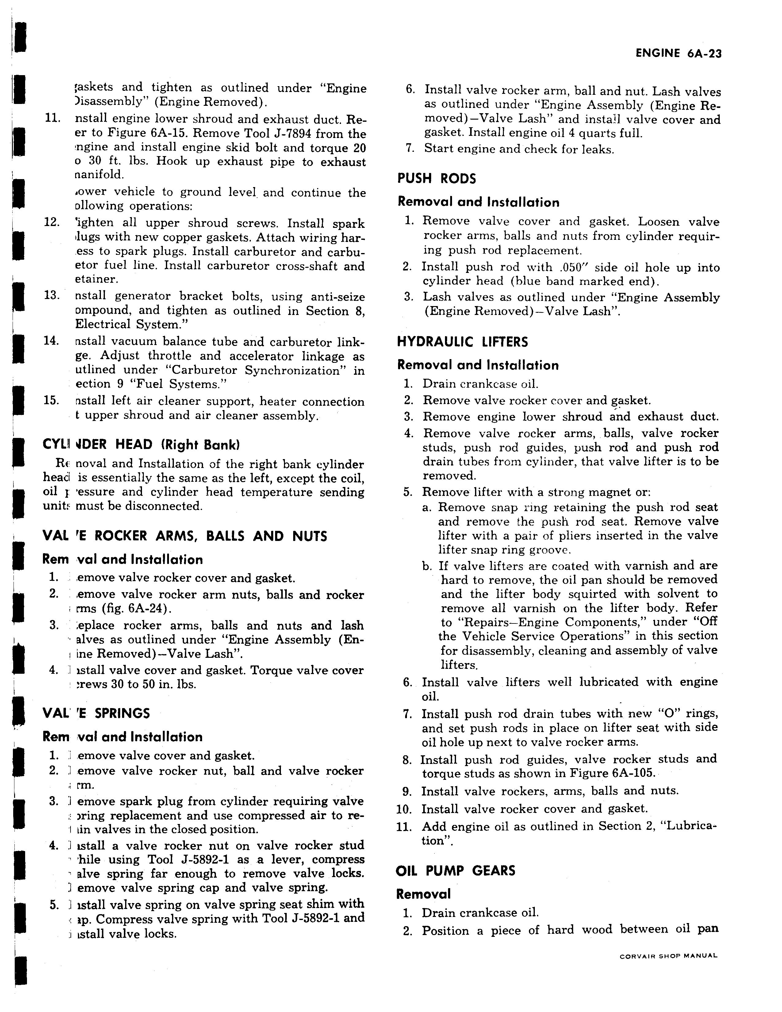
askets and tighten as outlined under Engine isassembly Engine Removed 11 nstall engine lower shroud and exhaust duct Reer to Figure 6A 15 Remove Tool J 7894 from the ngine and install engine skid bolt and torque 20 0 30 ft lbs Hook up exhaust pipe to exhaust nanifold oower vehicle to ground level and continue the ollowing operations 12 ighten all upper shroud screws Install spark vlugs with new copper gaskets Attach wiring haress to spark plugs Install carburetor and carbuetor fuel line Install carburetor cross shaft and I etainer 13 nstall generator bracket bolts using anti seize ompound and tighten as outlined in Section 8 Electrical System t 14 nstall vacuum balance tube and carburetor linkge Adjust throttle and accelerator linkage as utlined under Carburetor Synchronization in ection 9 Fuel Systems 15 nstall left air cleaner support heater connection t upper shroud and air cleaner assembly CYL I JDER HEAD Right Bank RE noval and Installation of the right bank cylinder head is essentially the same as the left except the coil oil 1 essure and cylinder head temperature sending unit must be disconnected VAL E ROCKER ARMS BALLS AND NUTS Rem val and Installation 1 emove valve rocker cover and gasket I 2 emove valve rocker arm nuts balls and rocker i rms fig 6A 24 3 eplace rocker arms balls and nuts and lash alves as outlined under Engine Assembly Eni ine Removed Valve Lash 4 i istall valve cover and gasket Torque valve cover rews 30 to 50 in lbs VAL E SPRINGS Rem val and Installation 1 emove valve cover and gasket 2 1 emove valve rocker nut ball and valve rocker a rm 3 I emove spark plug from cylinder requiring valve ring replacement and use compressed air to re1 iin valves in the closed position 4 a istall a valve rocker nut on valve rocker stud hile using Tool J 5892 1 as a lever compress e alve spring far enough to remove valve locks I emove valve spring cap and valve spring 5 I istall valve spring on valve spring seat shim with ip Compress valve spring with Tool J 5892 1 and i Lstall valve locks 6 Install valve rocker arm ball and nut Lash valves as outlined under Engine Assembly Engine Removed Valve Lash and install valve cover and gasket Install engine oil 4 quarts full 7 Start engine and check for leaks PUSH RODS Removal and Installation 1 Remove valve cover and gasket Loosen valve rocker arms balls and nuts from cylinder requiring push rod replacement 2 Install push rod with 050 side oil hole up into cylinder head blue band marked end 3 Lash valves as outlined under Engine Assembly Engine Removed Valve Lash HYDRAULIC LIFTERS Removal and Installation 1 Drain crankcase oil 2 Remove valve rocker cover and gasket 3 Remove engine lower shroud and exhaust duct 4 Remove valve rocker arms balls valve rocker studs push rod guides push rod and push rod drain tubes from cylinder that valve lifter is to be removed 5 Remove lifter with a strong magnet or a Remove snap ring retaining the push rod seat and remove the push rod seat Remove valve lifter with a pair of pliers inserted in the valve lifter snap ring groove b If valve lifters are coated with varnish and are hard to remove the oil pan should be removed and the lifter body squirted with solvent to remove all varnish on the lifter body Refer to Repairs Engine Components under Off the Vehicle Service Operations in this section for disassembly cleaning and assembly of valve lifters 6 Install valve lifters well lubricated with engine oil 7 Install push rod drain tubes with new O rings and set push rods in place on lifter seat with side oil hole up next to valve rocker arms 8 Install push rod guides valve rocker studs and torque studs as shown in Figure 6A 105 9 Install valve rockers arms balls and nuts 10 Install valve rocker cover and gasket 11 Add engine oil as outlined in Section 2 Lubrication OIL PUMP GEARS Removal 1 Drain crankcase oil 2 Position a piece of hard wood between oil pan

 Next
Next