Jeep Parts Wiki | Ford Parts Wiki
Home | Search | Browse
Prev

 Next
Next
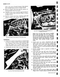
6 Disconnect fuel line and choke cable at carburetor Remove carburetor attaching stud nuts from arburetor and remove left carburetor Remove utboard carburetor stud long stud from carbu etor mounting pad 7 Remove vacuum balance tube from carburetor nounting flange as shown in Figure 6A 22 Renove generator bracket mounting bolts fig iA 22 and swivel generator bracket up away rom the engine upper shroud VACUUM BALANCE TUBE 1 r GENERATOR BRACE CARBURETOR w MOUNTING FLANGE Fig 6A 22 Engine Compartment Cylinder Head Removal and Installation r 8 emove wires and spark plugs from cylinder head emove spark plug gaskets and discard 9 i oosen all engine side shield retaining screws and a move screw from engine side shield under car I uretor in engine compartment attached to cyl i ider head fig 6A 13 Remove engine side shield i ig 6A 14 10 I emove oil cooler access hole cover and remove oil 1 oler this allows engine rear shroud freedom of a iovement during cylinder head removal 11 I sise vehicle on a hoist and attach Tool J 7894 as c rtlined in Section 6 12 I emove both engine side seal retainers and engine r rar seal retainers 13 emove the engine rear center shield and seal 4 ssembly fig 6A 11 14 f emove lower engine shroud and exhaust duct re 1 ining screws and bolts and remove engine lower troud and exhaust duct Remove exhaust pipe to r anifold nuts I 15 1 pen french locks on the exhaust manifold and r move holding clamp nuts fig 6A 38 Remove e chaust manifold and discard gaskets r Fig 6A 23 Engine Assembly Showing Access to Cylinder Head 16 Remove engine rear mounting cotter pin nut and washer from rear mounting bracket bolt 17 Remove four valve rocker arm cover screws and remove valve rocker cover while holding a pan below to catch oil draining from cylinder head 18 Remove rocker arm nuts balls and rocker arms Remove push rods valve rocker studs and push rod guides fig 6A 24 19 Remove O rings from cylinder head 20 Remove O rings from bottom of push rod drain w f I Fig 6A 24 Removal and Installation of Volvo Rocker Arms Balls and Nuts

 Next
Next