Jeep Parts Wiki | Ford Parts Wiki
Home | Search | Browse
Prev

 Next
Next
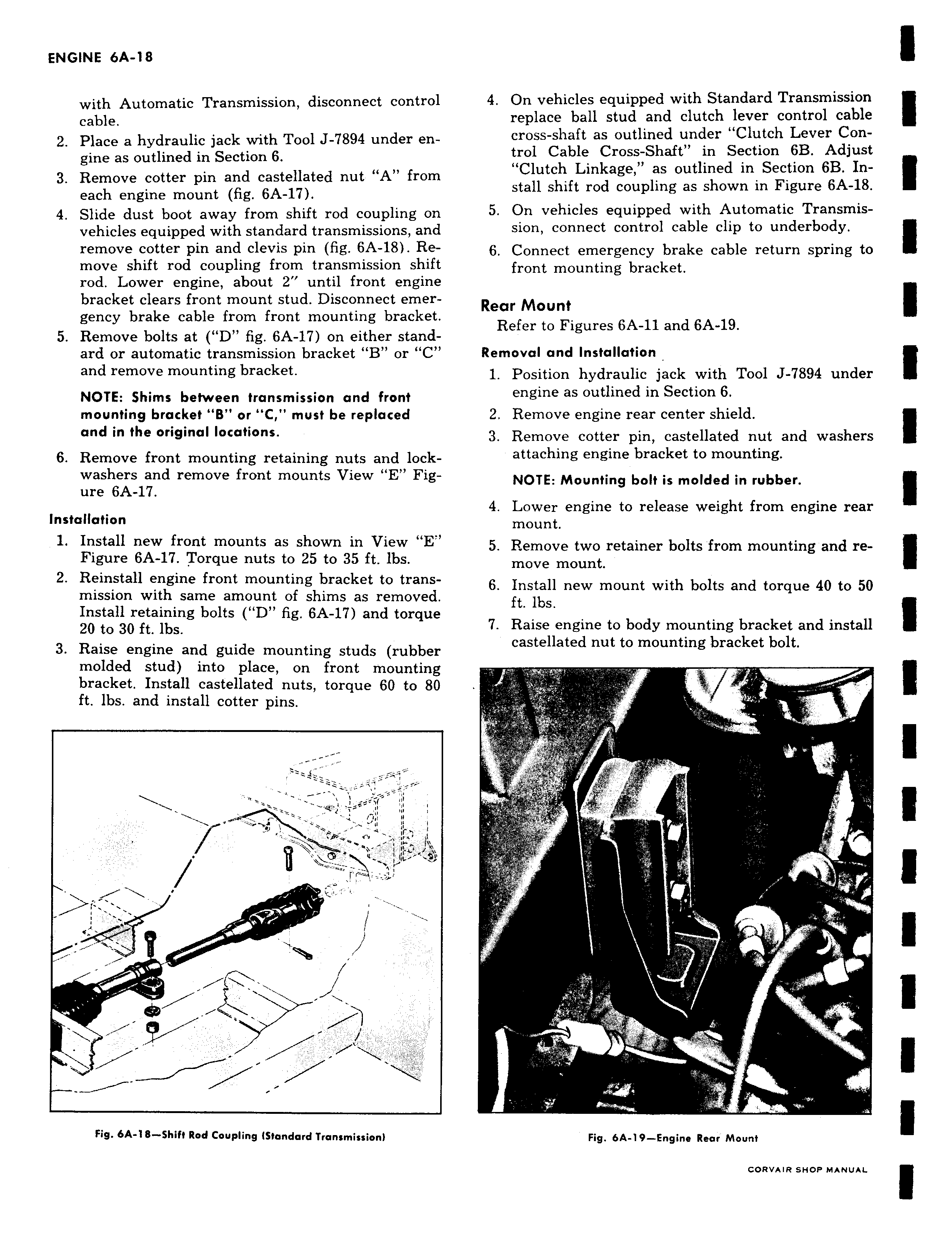
with Automatic Transmission disconnect control cable 2 Place a hydraulic jack with Tool J 7894 under engine as outlined in Section 6 3 Remove cotter pin and castellated nut A from each engine mount fig 6A 17 4 Slide dust boot away from shift rod coupling on vehicles equipped with standard transmissions and remove cotter pin and clevis pin fig 6A 18 Re move shift rod coupling from transmission shift rod Lower engine about 2 until front engine bracket clears front mount stud Disconnect emergency brake cable from front mounting bracket 5 Remove bolts at D fig 6A 17 on either standard or automatic transmission bracket B or C and remove mounting bracket NOTE Shims between transmission and front mounting bracket B or C must be replaced and in the original locations 6 Remove front mounting retaining nuts and lockwashers and remove front mounts View E Figure 6A 17 Installation 1 Install new front mounts as shown in View E Figure 6A 17 Torque nuts to 25 to 35 ft lbs 2 Reinstall engine front mounting bracket to transmission with same amount of shims as removed Install retaining bolts D fig 6A 17 and torque 20 to 30 ft lbs 3 Raise engine and guide mounting studs rubber molded stud into place on front mounting bracket Install castellated nuts torque 60 to 80 ft lbs and install cotter pins 1 i J Fig 6A 18 Shift Rod Coupling ISfandard Transmission 4 On vehicles equipped with Standard Transmission replace ball stud and clutch lever control cable cross shaft as outlined under Clutch Lever Con trol Cable Cross Shaft in Section 6B Adjust Clutch Linkage as outlined in Section 6B Install shift rod coupling as shown in Figure 6A 18 5 On vehicles equipped with Automatic Transmission connect control cable clip to underbody 6 Connect emergency brake cable return spring to front mounting bracket Rear Mount Refer to Figures 6A 11 and 6A 19 Removal and Installation 1 Position hydraulic jack with Tool J 7894 under engine as outlined in Section 6 2 Remove engine rear center shield 3 Remove cotter pin castellated nut and washers attaching engine bracket to mounting NOTE Mounting bolt is molded in rubber 4 Lower engine to release weight from engine rear mount 5 Remove two retainer bolts from mounting and remove mount 6 Install new mount with bolts and torque 40 to 50 ft lbs 7 Raise engine to body mounting bracket and install castellated nut to mounting bracket bolt sa y 4 T t J Fig 6A 19 Engine Rear Mount

 Next
Next