Jeep Parts Wiki | Ford Parts Wiki
Home | Search | Browse
Prev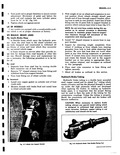
 Next
Next
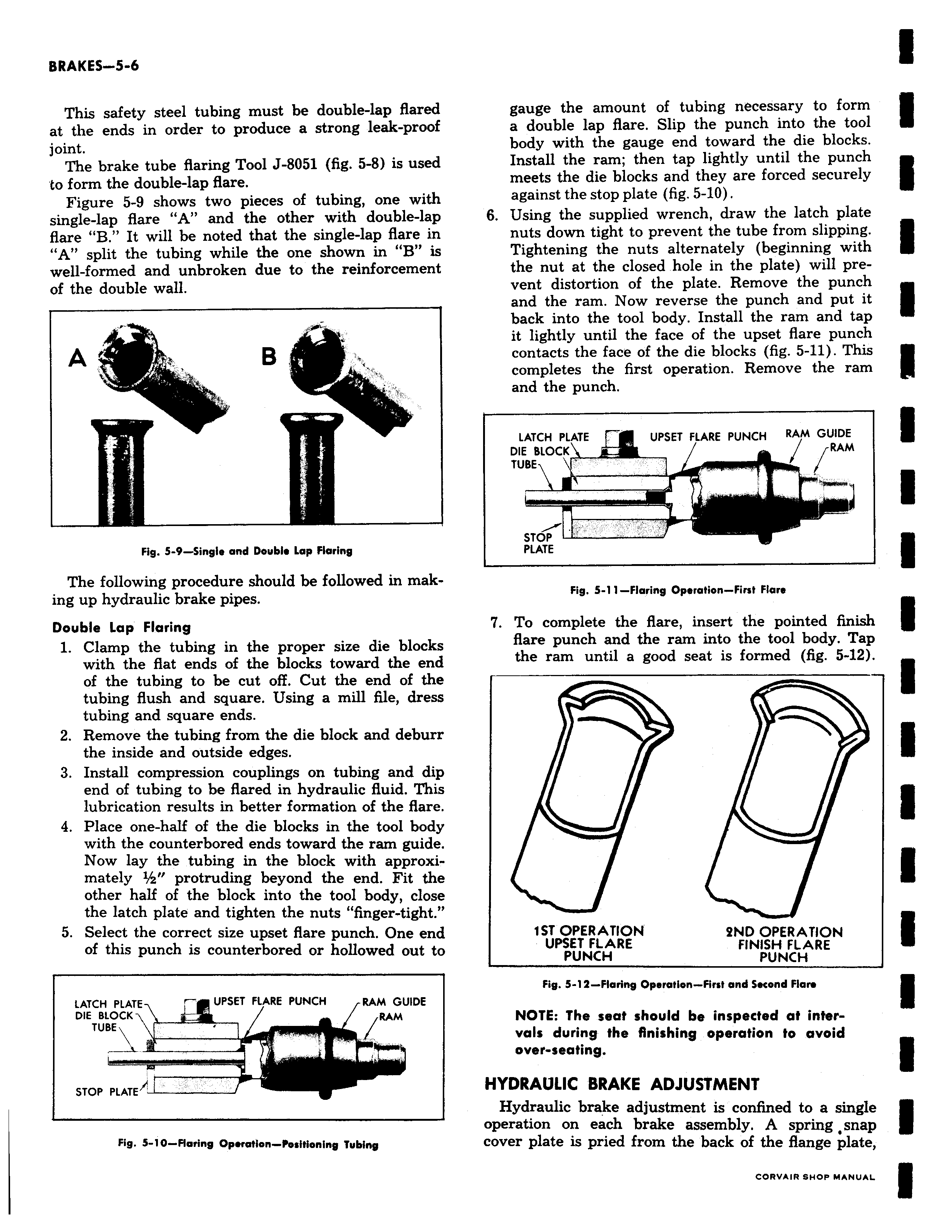
This safety steel tubing must be double lap flared at the ends in order to produce a strong leak proof joint The brake tube flaring Tool J 8051 fig 5 8 is used to form the double lap flare Figure 5 9 shows two pieces of tubing one with single lap flare A and the other with double lap flare B It will be noted that the single lap flare in A split the tubing while the one shown in B is well formed and unbroken due to the reinforcement of the double wall Fig S 9 Single and Double Lap Flaring The following procedure should be followed in making up hydraulic brake pipes Double Lap Flaring 1 Clamp the tubing in the proper size die blocks with the flat ends of the blocks toward the end of the tubing to be cut off Cut the end of the tubing flush and square Using a mill file dress tubing and square ends 2 Remove the tubing from the die block and deburr the inside and outside edges 3 Install compression couplings on tubing and dip end of tubing to be flared in hydraulic fluid This lubrication results in better formation of the flare 4 Place one half of the die blocks in the tool body with the counterbored ends toward the ram guide Now lay the tubing in the block with approximately protruding beyond the end Fit the other half of the block into the tool body close the latch plate and tighten the nuts finger tight 5 Select the correct size upset flare punch One end of this punch is counterbored or hollowed out to LATCH PLATE r UPSET FLARE PUNCH RAM GUIDE DIE BLOCK 4 RAM TUB T STOP PLATE Fig 5 10 Flaring OperMion Positioning Tubing gauge the amount of tubing necessary to form a double lap flare Slip the punch into the tool body with the gauge end toward the die blocks Install the ram then tap lightly until the punch meets the die blocks and they are forced securely against the stop plate fig 5 10 6 Using the supplied wrench draw the latch plate nuts down tight to prevent the tube from slipping Tightening the nuts alternately beginning with the nut at the closed hole in the plate will prevent distortion of the plate Remove the punch and the ram Now reverse the punch and put it back into the tool body Install the ram and tap it lightly until the face of the upset flare punch contacts the face of the die blocks fig 5 11 This completes the first operation Remove the ram and the punch LATCH PLATE UPSET FLARE PUNCH RAM GUIDE DIE BLOCK RAM TUBE I STOP PLATE Fig 5 11 Flaring Operation First Flare 7 To complete the flare insert the pointed finish flare punch and the ram into the tool body Tap the ram until a good seat is formed fig 5 12 1ST OPERATION 2ND OPERATION UPSET FLARE FINISH FLARE PUNCH PUNCH Fig 5 14 Flaring Operation First and Second Flan NOTE The seat should be inspected at intervals during the finishing operation to avoid over seating HYDRAULIC BRAKE ADJUSTMENT Hydraulic brake adjustment is confined to a single operation on each brake assembly A spring snap cover plate is pried from the back of the flange plate