Jeep Parts Wiki | Ford Parts Wiki
Home | Search | Browse
Prev
 Next
Next
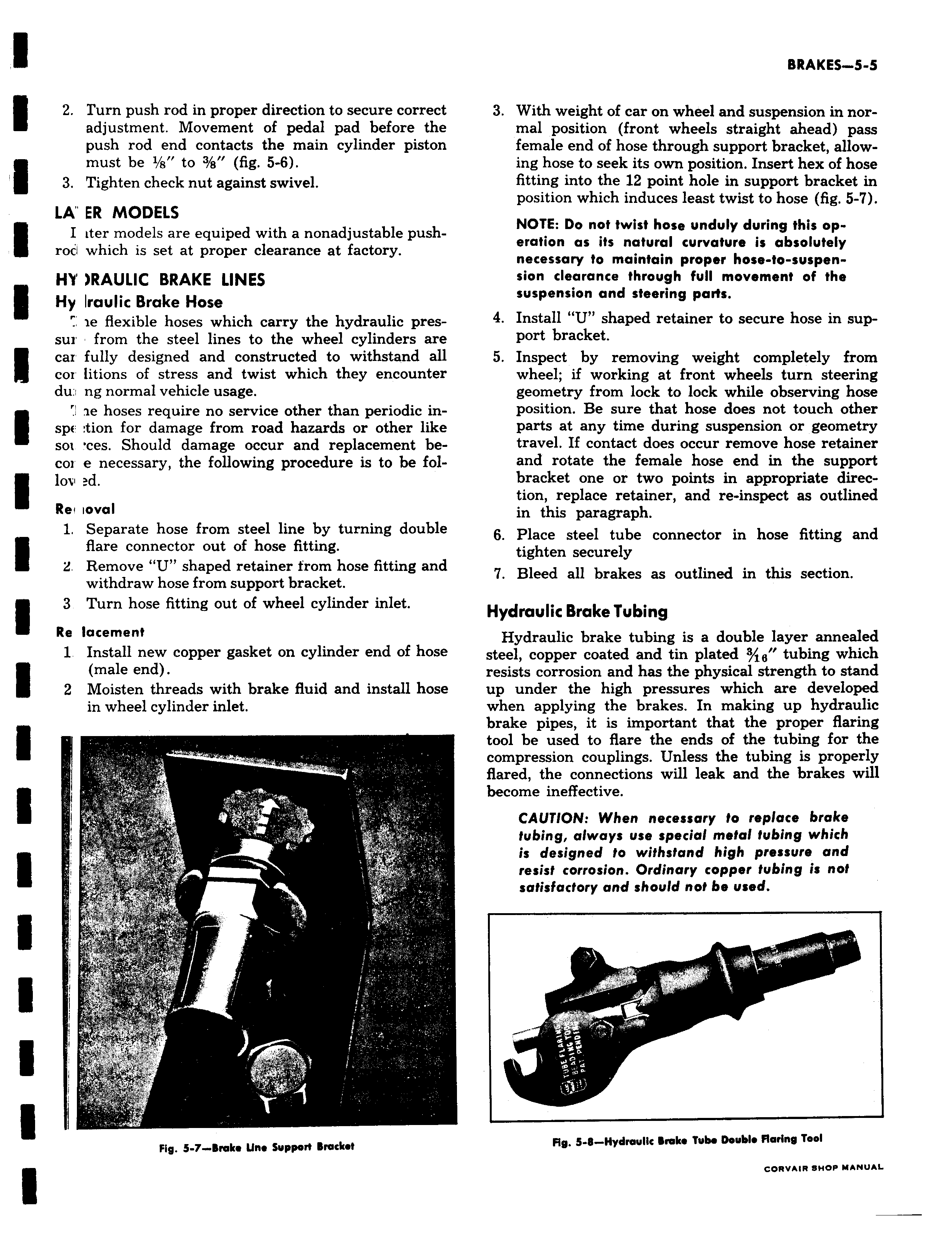
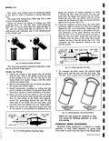
2 Turn push rod in proper direction to secure correct adjustment Movement of pedal pad before the push rod end contacts the main cylinder piston must be 1 a to 3 s fig 5 6 3 Tighten check nut against swivel LA ER MODELS I iter models are equiped with a nonadjustable push roci which is set at proper clearance at factory r HY RAULIC BRAKE LINES Hy Iraulic Brake Hose ie flexible hoses which carry the hydraulic pressur from the steel lines to the wheel cylinders are I car fully designed and constructed to withstand all coi litions of stress and twist which they encounter du ng normal vehicle usage ae hoses require no service other than periodic in spE lion for damage from road hazards or other like sox ces Should damage occur and replacement becor e necessary the following procedure is to be fol lov d Re ioval 1 Separate hose from steel line by turning double flare connector out of hose fitting L Remove U shaped retainer from hose fitting and withdraw hose from support bracket 3 Turn hose fitting out of wheel cylinder inlet Re lacement 1 Install new copper gasket on cylinder end of hose male end 2 Moisten threads with brake fluid and install hose in wheel cylinder inlet c rt tv 7 r YF 4 n kI y 5 Fig 5 7 Broke tlne support Bracket 3 With weight of car on wheel and suspension in normal position front wheels straight ahead pass female end of hose through support bracket allow ing hose to seek its own position Insert hex of hose fitting into the 12 point hole in support bracket in position which induces least twist to hose fig 5 7 NOTE Do not twist hose unduly during this operation as its natural curvature is absolutely necessary to maintain proper hose to suspension clearance through full movement of the suspension and steering parts 4 Install U shaped retainer to secure hose in support bracket 5 Inspect by removing weight completely from wheel if working at front wheels turn steering geometry from lock to lock while observing hose position Be sure that hose does not touch other parts at any time during suspension or geometry travel If contact does occur remove hose retainer and rotate the female hose end in the support bracket one or two points in appropriate direction replace retainer and re inspect as outlined in this paragraph 6 Place steel tube connector in hose fitting and tighten securely 7 Bleed all brakes as outlined in this section Hydraulic Brake Tubing Hydraulic brake tubing is a double layer annealed steel copper coated and tin plated g tubing which resists corrosion and has the physical strength to stand up under the high pressures which are developed when applying the brakes In making up hydraulic brake pipes it is important that the proper flaring tool be used to flare the ends of the tubing for the compression couplings Unless the tubing is properly flared the connections will leak and the brakes will become ineffective CAUTION When necessary to replace brake tubing always use special metal tubing which is designed to withstand high pressure and resist corrosion Ordinary copper tubing is not satisfactory and should not be used 7 F Fig 5 8 Hydwullc brake Tube Double Flaring Tool