Jeep Parts Wiki | Ford Parts Wiki
Home | Search | Browse
|
Corvair Chassis Shop Manual December 1964 |
|
Prev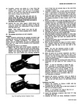
 Next
Next
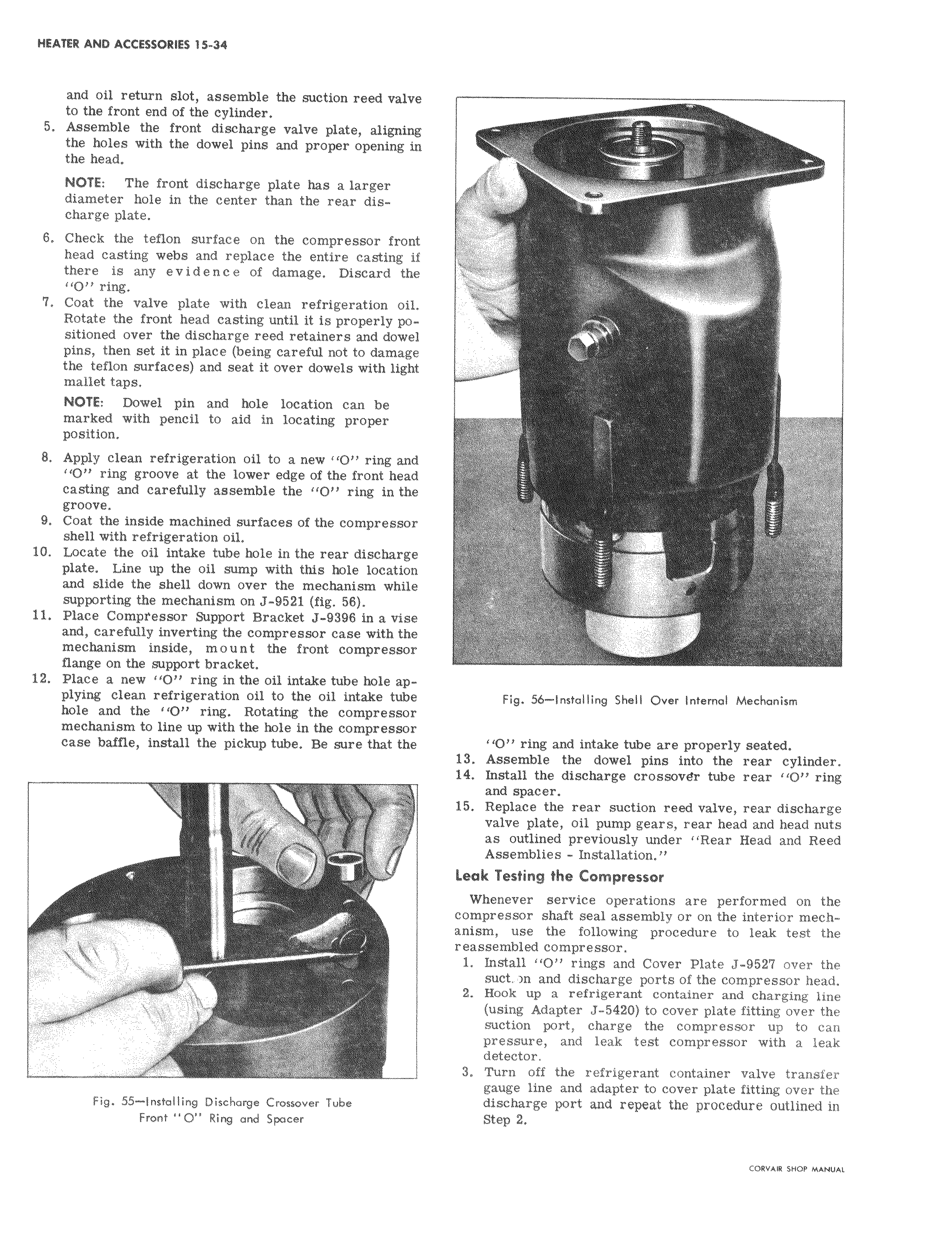
and oil return slot assemble the suction reed valve to the front end of the cylinder 5 Assemble the front discharge valve plate aligning the holes with the dowel pins and proper opening in i the head NOTE The front discharge plate has a larger diameter hole in the center than the rear dis charge plate 6 Check the teflon surface on the compressor front head casting webs and replace the entire casting if there is any evidence of damage Discard the O ring 7 Coat the valve plate with clean refrigeration oil Rotate the front head casting until it is properly positioned over the discharge reed retainers and dowel pins then set it in place being careful not to damage the teflon surfaces and seat it over dowels with light mallet taps NOTE Dowel pin and hole location can be marked with pencil to aid in locating proper position 8 Apply clean refrigeration oil to a new 1O ring and O ring groove at the lower edge of the front head casting and carefully assemble the O ring in the groove 9 Coat the inside machined surfaces of the compressor shell with refrigeration oil 10 Locate the oil intake tube hole in the rear discharge plate Line up the oil sump with this hole location and slide the shell down over the mechanism while supporting the mechanism on J 9521 fig 58 il Place Compressor Support Bracket J 9396 in a vise and carefully inverting the compressor case with the mechanism inside mount the front compressor flange on the support bracket 12 Place a new O ring in the oil intake tube hole applying clean refrigeration oil to the oil intake tube I hole and the 110 ring Rotating the compressor mechanism to line up with the hole in the compressor case baffle install the pickup tube Be sure that the i S Fig 55 Installing Discharge Crossover Tube Front O Ring and Spacer y Fig 56 Installing Shell Over Internal Mechanism O ring and intake tube are properly seated 13 Assemble the dowel pins into the rear cylinder 14 Install the discharge crossov8r tube rear O ring and spacer 15 Replace the rear suction reed valve rear discharge valve plate oil pump gears rear head and head nuts as outlined previously under Rear Head and Reed Assemblies Installation Leak Testing the Compressor Whenever service operations are performed on the compressor shaft seal assembly or on the interior mechanism use the following procedure to leak test the reassembled compressor 1 Install O rings and Cover Plate J 9527 over the suet n and discharge ports of the compressor head 2 Hook up a refrigerant container and charging line usin Adapter J 5420 to cover plate fitting over the suction port charge the compressor up to can pressure and leak test compressor with a leak detector 3 Turn off the refrigerant container valve transfer gauge line and adapter to cover plate fitting over the discharge port and repeat the procedure outlined in Step Z