Jeep Parts Wiki | Ford Parts Wiki
Home | Search | Browse
|
Corvair Chassis Shop Manual December 1964 |
|
Prev
 Next
Next
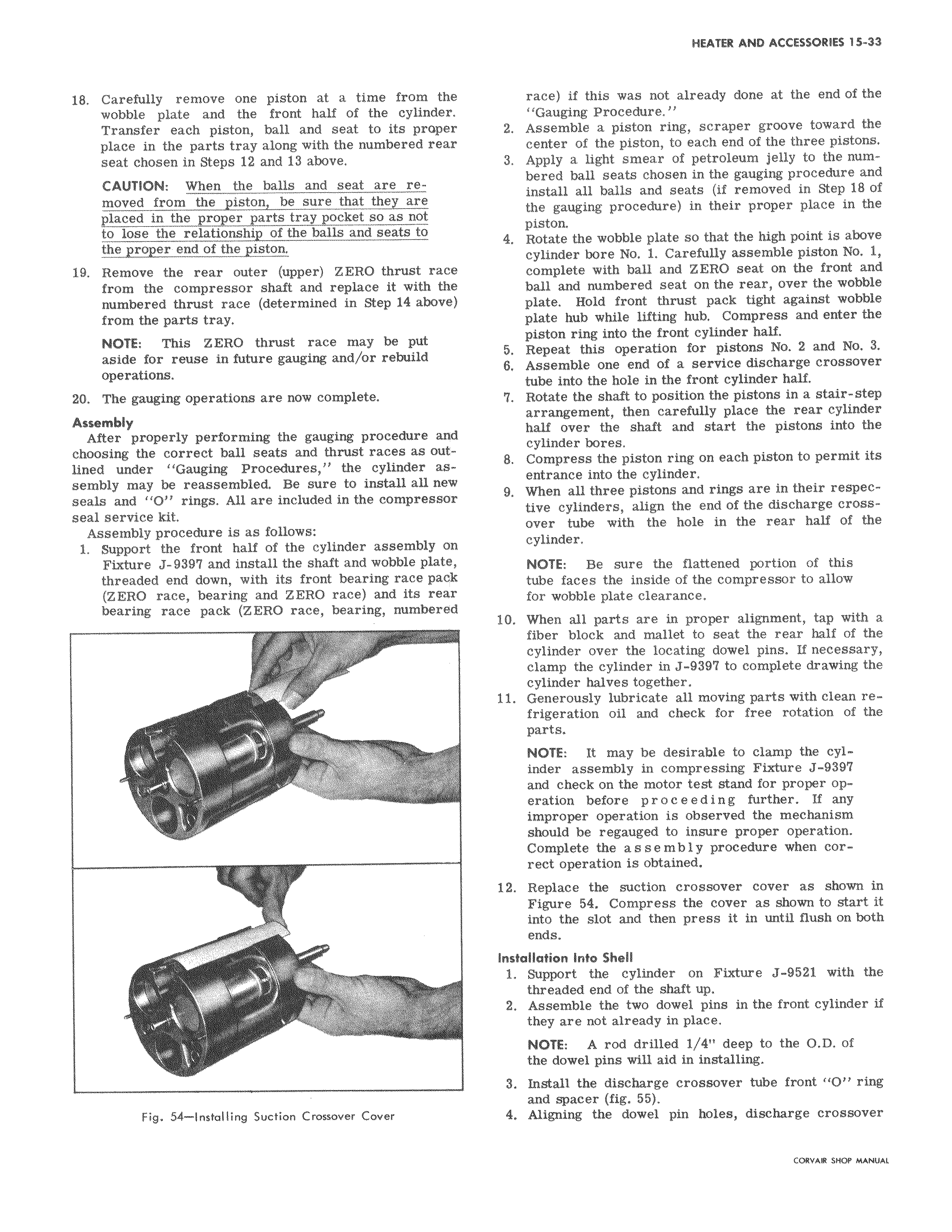
18 Carefully remove one piston at a time from th wobble plate and the front half of the cylinder Transfer each piston ball and seat to its prope place in the parts tray along with the numbered rea seat chosen in Steps 12 and 13 above CAUTION When the balls and seat are removed from the piston be sure that they are placed in the proper parts tray pocket so as not to lose the relationship of the balls and seats to the proper end of the piston 19 Remove the rear outer upper ZERO thrust rae4 from the compressor shaft and replace it with tbo numbered thrust race determined in Step 14 above from the parts tray NOTE This ZERO thrust race may be put aside for reuse in future gauging and or rebuild operations 20 The gauging operations are now complete Assembly After properly performing the gauging procedure anc choosing the correct ball seats and thrust races as outlined under Gauging Procedures the cylinder assembly may be reassembled Be sure to install all nea seals and O rings All are included in the compressoi seal service kit Assembly procedure is as follows 1 Support the front half of the cylinder assembly or Fixture J 9397 and install the shaft and wobble plate threaded end down with its front bearing race pact ZERO race bearing and ZERO race and its rear bearing race pack ZERO race bearing numbered t Fig 54 Installing Suction Crossover Cover race if this was not already done at the end of the Gauging Procedure 2 Assemble a piston ring scraper groove toward the center of the piston to each end of the three pistons 3 Apply a light smear of petroleum jelly to the numbered ball seats chosen in the gauging procedure and install all balls and seats if removed in Step 18 of the gauging procedure in their proper place in the piston 4 Rotate the wobble plate so that the high point is above cylinder bore No 1 Carefully assemble piston No 1 complete with ball and ZERO seat on the front and ball and numbered seat on the rear over the wobble I plate Hold front thrust pack tight against wobble plate hub while lifting hub Compress and enter the piston ring into the front cylinder half 5 Repeat this operation for pistons No 2 and No 3 6 Assemble one end of a service discharge crossover tube into the hole in the front cylinder half 7 Rotate the shaft to position the pistons in a stair step arrangement then carefully place the rear cylinder half over the shaft and start the pistons into the cylinder bores 8 Compress the piston ring on each piston to permit its entrance into the cylinder 9 When all three pistons and rings are in their respective cylinders align the end of the discharge crossover tube with the hole in the rear half of the cylinder NOTE Be sure the flattened portion of this tube faces the inside of the compressor to allow for wobble plate clearance 10 When all parts are in proper alignment tap with a fiber block and mallet to seat the rear half of the cylinder over the locating dowel pins If necessary clamp the cylinder in J 9397 to complete drawing the cylinder halves together 11 Generously lubricate all moving parts with clean refrigeration oil and check for free rotation of the parts NOTE It may be desirable to clamp the cylinder assembly in compressing Fixture J 9397 and check on the motor test stand for proper operation before proceeding further If any improper operation is observed the mechanism should be regauged to insure proper operation Complete the assembly procedure when correct operation is obtained 12 Replace the suction crossover cover as shown in Figure 54 Compress the cover as shown to start it into the slot and then press it in until flush on both ends Installation Into Shell 1 Support the cylinder on Fixture J 9521 with the threaded end of the shaft up 2 Assemble the two dowel pins in the front cylinder if they are not already in place NOTE A rod drilled 1 4 deep to the O D of the dowel pins will aid in installing 3 Install the discharge crossover tube front O ring and spacer fig 55 4 Aligning the dowel pin holes discharge crossover