Jeep Parts Wiki | Ford Parts Wiki
Home | Search | Browse | Marketplace | Messages | FAQ | Guest
|
Corvair Chassis Shop Manual December 1964 |
|
Prev

 Next
Next
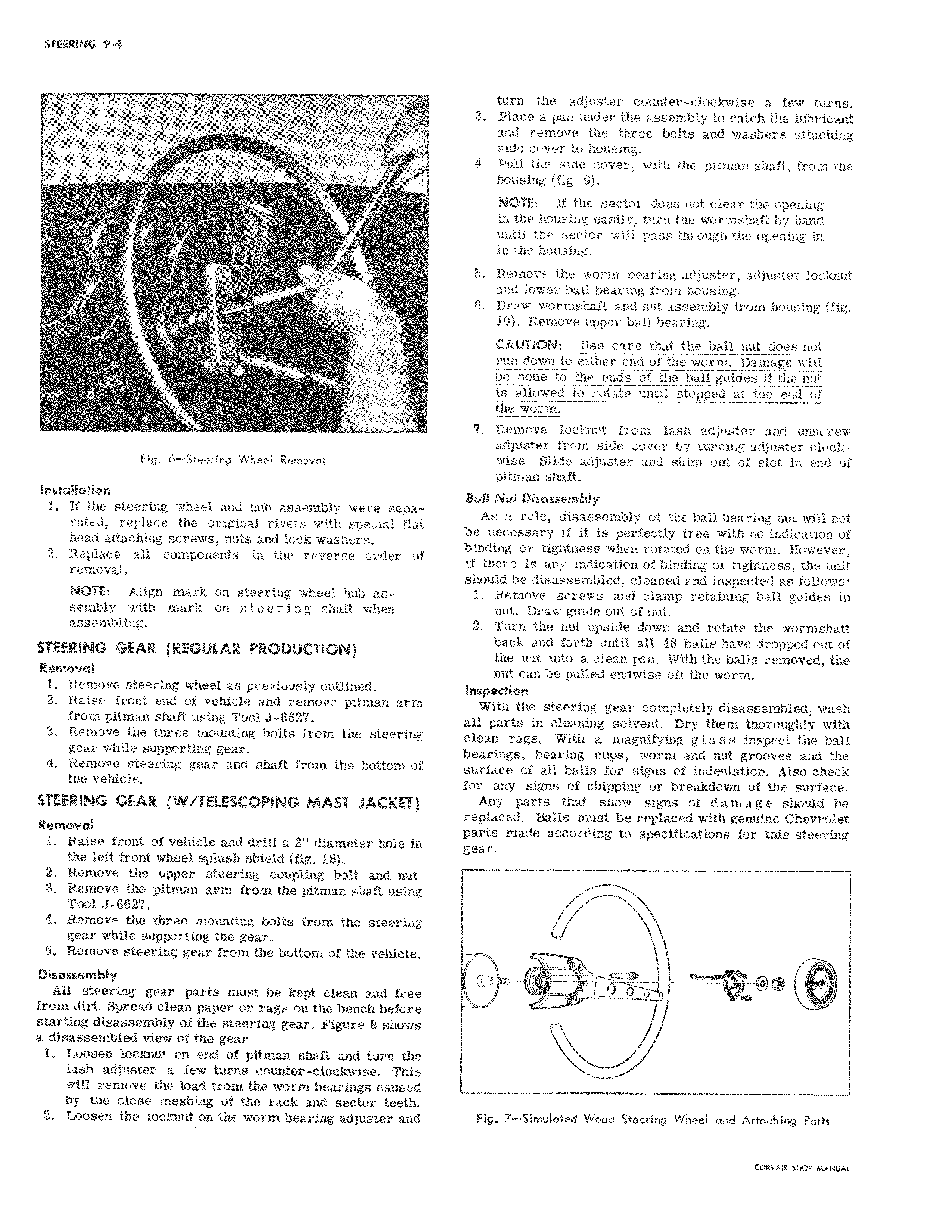
Fig 6 Steering Wheel Removal Installation 1 If the steering wheel and hub assembly were sepa rated replace the original rivets with special flat head attaching screws nuts and lock washers 2 Replace all components in the reverse order c f removal NOTE Align mark on steering wheel hub assembly with mark on steering shaft when I assembling STEERING GEAR REGULAR PRODUCTION Removal 1 Remove steering wheel as previously outlined 2 Raise front end of vehicle and remove pitman arm from pitman shaft using Tool J 6627 3 Remove the three mounting bolts from the steering gear while supporting gear 4 Remove steering gear and shaft from the bottom of the vehicle STEERING GEAR W TELESCOPING MAST JACKET Removal 1 Raise front of vehicle and drill a 2 diameter hole i the left front wheel splash shield fig 18 2 Remove the upper steering coupling bolt and nut 3 Remove the pitman arm from the pitman shaft using Tool J 6627 4 Remove the three mounting bolts from the steer gear while supporting the gear 5 Remove steering gear from the bottom of the vehiclI Disassembly All steering gear parts must be kept clean and free from dirt Spread clean paper or rags on the bench befor starting disassembly of the steering gear Figure 8 ahow a disassembled view of the gear 1 Loosen locknut on end of pitman shaft and turn the lash adjuster a few turns counter clockwise Thi will remove the load from the worm bearings cause by the close meshing of the rack and sector teeth 2 Loosen the locknut on the worm bearing adjuster and turn the adjuster counter clockwise a few turns 3 Pl e a pan under the assembly to catch the lubricant and remove the three bolts and washers attaching sidle cover to housing 4 PuX the side cover with the pitman shaft from the housing fig 9 NOTE If the sector does not clear the opening in the housing easily turn the wormshaft by hand until the sector will pass through the opening in in the housing 5 Remove the worm bearing adjuster adjuster locknut and lower ball bearing from housing 6 Draw wormshaft and nut assembly from housing fig 10 Remove upper ball bearing CAUTION Use care that the ball nut does not run down to either end of the worm Damage will be done to the ends of the ball guides if the nut is allowed to rotate until stopped at the end of the worm 7 Remove locknut from lash adjuster and unscrew adjuster from side cover by turning adjuster clockwise Slide adjuster and shim out of slot in end of pitman shaft Ball Nu Disassembly As a rule disassembly of the ball bearing nut will not be necessary if it is perfectly free with no indication of binding or tightness when rotated on the worm However if there is any indication of binding or tightness the unit should be disassembled cleaned and inspected as follows 1 Remove screws and clamp retaining ball guides in nut Draw guide out of nut 2 Turn the nut upside down and rotate the wormshaft back and forth until all 48 balls have dropped out of the nut into a clean pan With the balls removed the nut can be pulled endwise off the worm Inspection With the steering gear completely disassembled wash all parts in cleaning solvent Dry them thoroughly with clean rags With a magnifying g 1 a s s inspect the ball bearings bearing cups worm and nut grooves and the surfacei of all balls for signs of indentation Also check for any signs of chipping or breakdown of the surface Any parts that show signs of d a m a g e should be replaced Balls must be replaced with genuine Chevrolet parts nta de according to specifications for this steering gear 0 Fig 7 Simulated Wood Steering Wheel and Attaching Parts

 Next
Next