Jeep Parts Wiki | Ford Parts Wiki
Home | Search | Browse
|
Corvair Chassis Shop Manual December 1964 |
|
Prev

 Next
Next
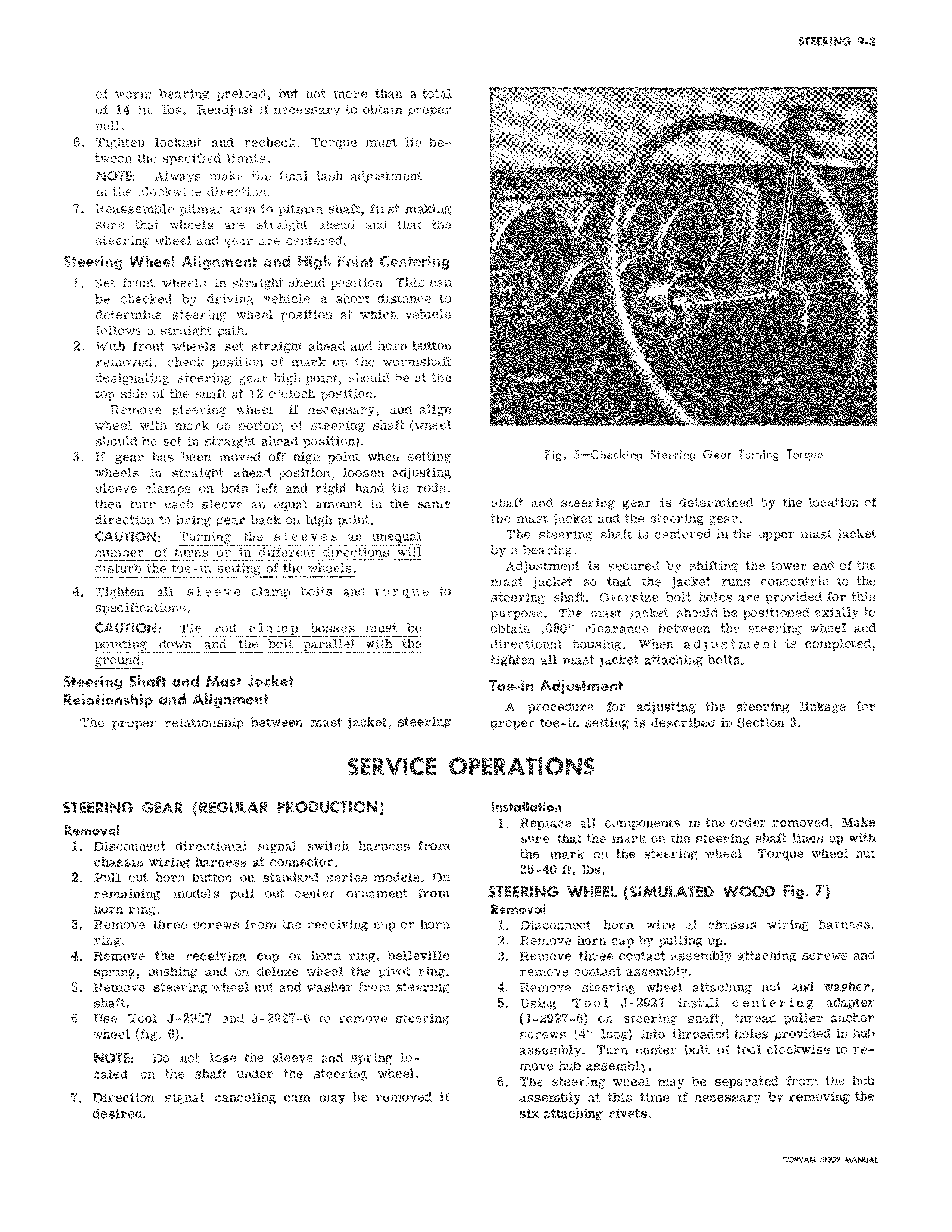
of worm bearing preload but not more than a total of 14 in lbs Readjust if necessary to obtain proper pull 6 Tighten locknut and recheck Torque must lie between the specified limits NOTE Always make the final lash adjustment in the clockwise direction 7 Reassemble pitman arm to pitman shaft first making sure that wheels are straight ahead and that the steering wheel and gear are centered Steering Wheel Alignment and High Point Centering 1 Set front wheels in straight ahead position This can be checked by driving vehicle a short distance to determine steering wheel position at which vehicle follows a straight path 2 With front wheels set straight ahead and horn button removed check position of mark on the wormshaft designating steering gear high point should be at the top side of the shaft at 12 o clock position Remove steering wheel if necessary and align wheel with mark on bottom of steering shaft wheel should be set in straight ahead position 3 If gear has been moved off high point when setting wheels in straight ahead position loosen adjusting sleeve clamps on both left and right hand tie rods then turn each sleeve an equal amount in the same direction to bring gear back on high point CAUTION Turning the sleeves an unequal number of turns or in different directions will disturb the toe in setting of the wheels 4 Tighten all sleeve clamp bolts and torque to specifications CAUTION Tie rod clamp bosses must be pointing down and the bolt parallel with the ground Steering Shaft and Mast Jacket Relationship and Alignment The proper relationship between mast jacket steering SERVICE 1 STEERING GEAR REGULAR PRODUCTION Removal 1 Disconnect directional signal switch harness from chassis wiring harness at connector 2 Pull out horn button on standard series models On remaining models pull out center ornament from horn ring 3 Remove three screws from the receiving cup or horn ring 4 Remove the receiving cup or horn ring belleville spring bushing and on deluxe wheel the pivot ring 5 Remove steering wheel nut and washer from steering shaft 6 Use Tool J 2927 and J 2927 6 to remove steering wheel fig 6 NOTE Do not lose the sleeve and spring located on the shaft under the steering wheel 7 Direction signal canceling cam may be removed if desired y i f li l u y r Y T i Fig 5 Checking Steering Gear Turning Torque shaft and steering gear is determined by the location of the mast jacket and the steering gear The steering shaft is centered in the upper mast jacket by a bearing Adjustment is secured by shifting the lower end of the mast jacket so that the jacket runs concentric to the steering shaft Oversize bolt holes are provided for this purpose The mast jacket should be positioned axially to obtain 080 clearance between the steering wheel and directional housing When adjustment is completed tighten all mast jacket attaching bolts Toe In Adjustment A procedure for adjusting the steering linkage for proper toe in setting is described in Section 3 PERATIONS Installation 1 Replace all components in the order removed Make sure that the mark on the steering shaft lines up with the mark on the steering wheel Torque wheel nut 35 40 ft lbs STEERING WHEEL SIMULATED WOOD Fig 7 Removal 1 Disconnect horn wire at chassis wiring harness 2 Remove horn cap by pulling up 3 Remove three contact assembly attaching screws and remove contact assembly 4 Remove steering wheel attaching nut and washer 5 Using Tool J 2927 install centering adapter J 2927 6 on steering shaft thread puller anchor screws 4 long into threaded holes provided in hub assembly Turn center bolt of tool clockwise to remove hub assembly 6 The steering wheel may be separated from the hub assembly at this time if necessary by removing the six attaching rivets CaRVAR Eqaf YANUAL

 Next
Next