Jeep Parts Wiki | Ford Parts Wiki
Home | Search | Browse
|
Corvair Chassis Shop Manual December 1964 |
|
Prev

 Next
Next
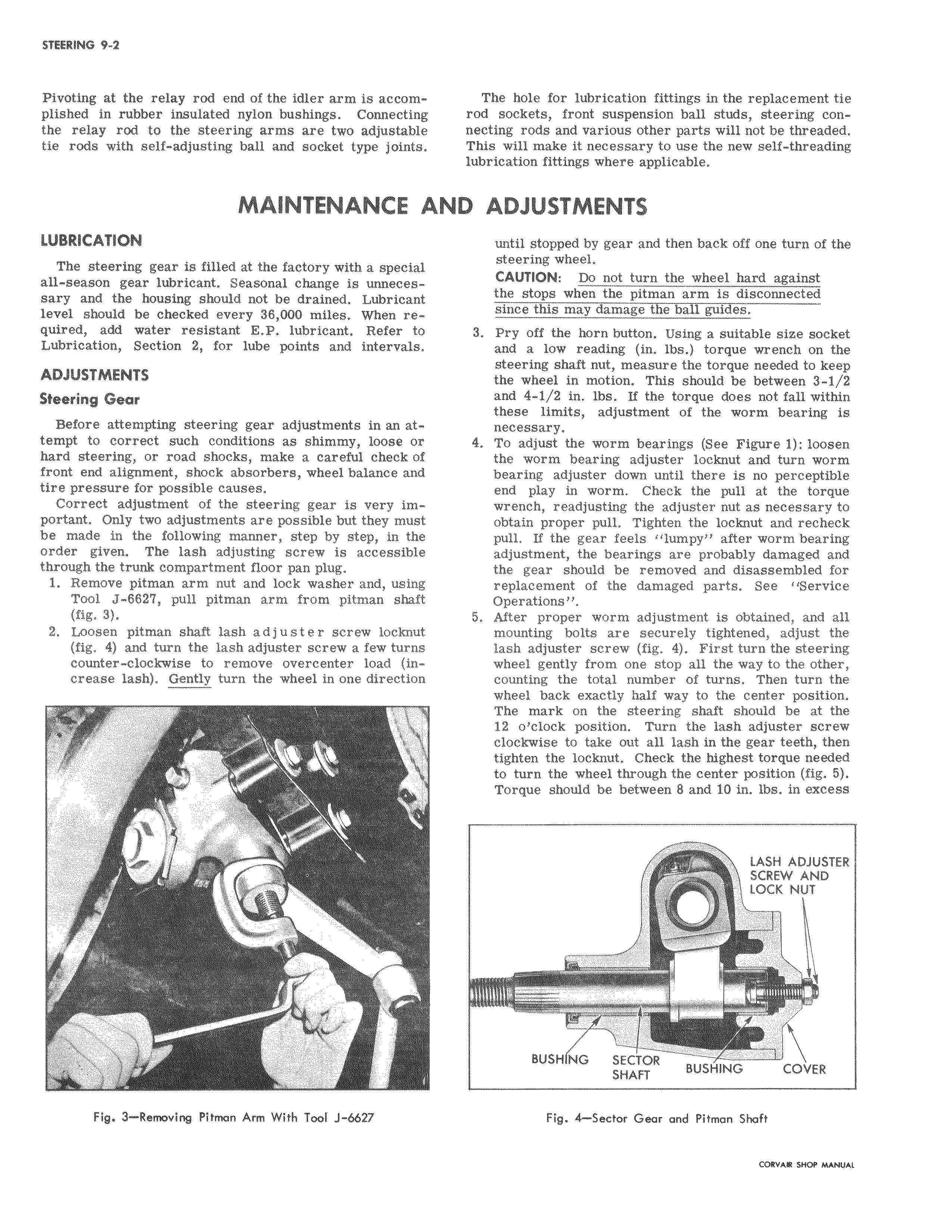
Pivoting at the relay rod end of the idler arm is accom plished in rubber insulated nylon bushings Connecting the relay rod to the steering arms are two adjustable tie rods with self adjusting ball and socket type joint MAINTENANCE AN LUBRICATION The steering gear is filled at the factory with a special all season gear lubricant Seasonal change is unneces sary and the housing should not be drained Lubricant level should be checked every 38 000 miles When re quired add water resistant E P lubricant Refer t Lubrication Section 2 for lube points and intervals ADJUSTMENTS I Steering Gear Before attempting steering gear adjustments in an at tempt to correct such conditions as shimmy loose o hard steering or road shocks make a careful check f front end alignment shock absorbers wheel balance and tire pressure for possible causes Correct adjustment of the steering gear is very important Only two adjustments are possible but they must be made in the following manner step by step in the order given The lash adjusting screw is acceasiblle through the trunk compartment floor pan plug 1 Remove pitman arm nut and lock washer and using Tool J 6627 pull pitman arm from pitman shaft fig 3 I 2 Loosen pitman shaft lash adjuster screw lockn Yt fig 4 and turn the lash adjuster screw a few turns counter clockwise to remove overcenter load crease lash Gently turn the wheel in one direction 1 i j 1 w ELM Fig 3 Removing Pitman Ann With Tool J 6627 The hole for lubrication fittings in the replacement tie rod sockets front suspension ball studs steering connecting rods and various other parts will not be threaded This will make it necessary to use the new self threading lubricat3on fittings where applicable D ADJUSTMENTS until stopped by gear and then back off one turn of the steering wheel CAUTION Do not turn the wheel hard against the stops when the pitman arm is disconnected since this may damage the ball guides 3 Pry off the horn button Using a suitable size socket and a low reading in lbs torque wrench on the steering shaft nut measure the torque needed to keep the wheel in motion This should be between 3 1 2 and 4 1 2 in lbs If the torque does not fall within these limits adjustment of the worm bearing is necessary 4 To adjust the worm bearings See Figure 1 loosen the worm bearing adjuster locknut and turn worm bearing adjuster down until there is no perceptible end play in worm Check the pull at the torque wrench readjusting the adjuster nut as necessary to obtain proper pull Tighten the locknut and recheck pull If the gear feels lumpy after worm bearing adjustment the bearings are probably damaged and the gear should be removed and disassembled for replacement of the damaged parts See Service Operations 5 After proper worm adjustment is obtained and all mounting bolts are securely tightened adjust the lash adjuster screw fig 4 First turn the steering wheel gently from one stop all the way to the other counting the total number of turns Then turn the wheel back exactly half way to the center position The mark on the steering shaft should be at the 12 o clock position Turn the lash adjuster screw clockwise to take out all lash in the gear teeth then tighten the locknut Check the highest torque needed to turn the wheel through the center position fig 5 Torque should be between 8 and 10 in lbs in excess LASH ADJUSTER SCREW AND LOCK NUT i BUSH NG SECTOR SHAFT BUSHING COVER Fig 4 Sector Gear and Pitman Shaft

 Next
Next