Jeep Parts Wiki | Ford Parts Wiki
Home | Search | Browse
|
Corvair Chassis Shop Manual December 1964 |
|
Prev
 Next
Next
910111
910111
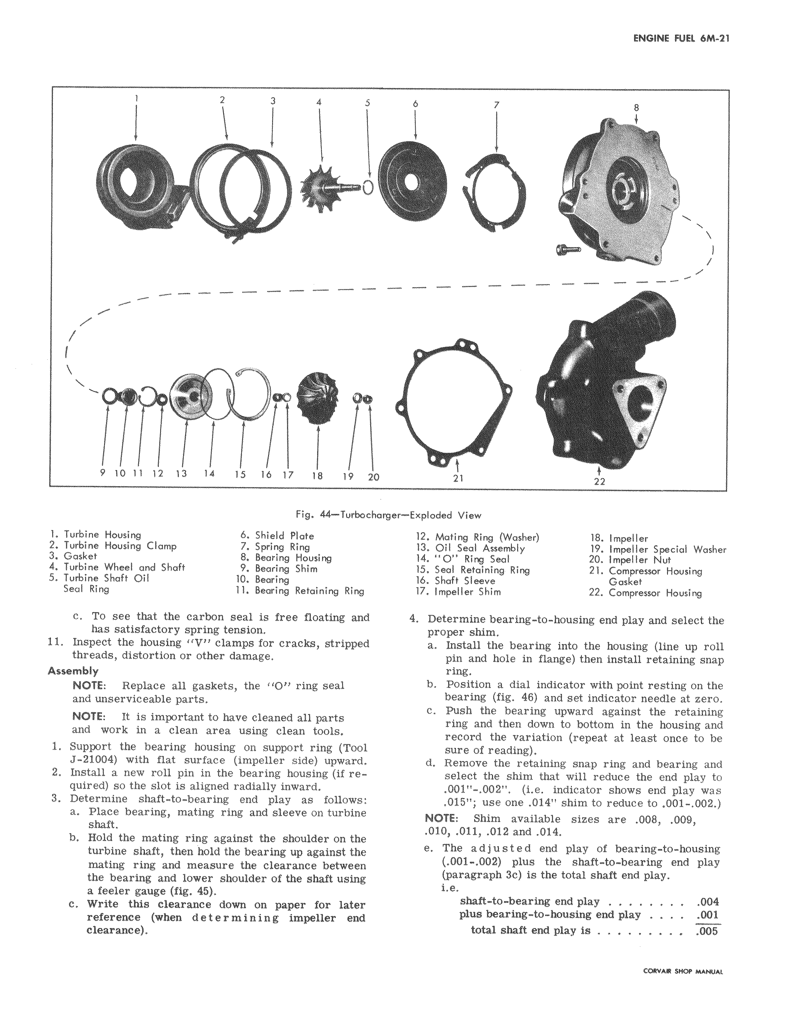
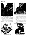
1 2 3 4 r w 190O v Soo 910111 2 13 14 15 16 17 18 19 2t Fig 44 Turbocb 1 Turbine Housing 6 Shield plate 2 Turbine Housing Clomp 7 Spring Ring 3 Gasket 8 Bearing Housing 4 Turbine Wheel and Shaft 9 Bearing Shim 5 Turbine Shaft Oil 10 Bearing Seal Ring 11 Bearing Retaining Ring c To see that the carbon seal is free floating and has satisfactory spring tension 11 Inspect the housing IV clamps for cracks stripped threads distortion or other damage Assembly NOTE Replace all gaskets the 1 O ring seal and unserviceable parts NOTE It is important to have cleaned all parts and work in a clean area using clean tools 1 Support the bearing housing on support ring Tool J 21004 with flat surface impeller side upward 2 Install a new roll pin in the bearing housing if required so the slot is aligned radially inward 3 Determine shaft to bearing end play as follows a Place bearing mating ring and sleeve on turbine shaft b Hold the mating ring against the shoulder on the turbine shaft then hold the bearing up against the mating ring and measure the clearance between the bearing and lower shoulder of the shaft using a feeler gauge fig 45 c Write this clearance down on paper for later reference when determining impeller end clearance 6 7 8 s e 0 C t t 21 22 rger Exploded View 12 Mating Ring Washer 18 Impeller 13 Oil Seal Assembly 19 Impeller Special Washer 14 O Ring Seal 20 Impeller Nut 15 Seal Retaining Ring 21 Compressor Housing 16 Shaft Sleeve Gasket 17 Impeller Shim 22 Compressor Housing 4 Determine bearing to housing end play and select the proper shim a Install the bearing into the housing line up roll pin and hole in flange then install retaining snap ring b Position a dial indicator with point resting on the bearing fig 46 and set indicator needle at zero c Push the bearing upward against the retaining ring and then down to bottom in the housing and record the variation repeat at least once to be sure of reading d Remove the retaining snap ring and bearing and select the shim that will reduce the end play to 001 002 i e indicator shows end play was 015 use one 014 shim to reduce to 001 002 NOTE Shim available sizes are 008 009 010 011 012and 014 e The adjusted end play of bearing to housing 001 002 plus the shaft to bearing end play paragraph 3c is the total shaft end play i e shaft to bearing end play 004 plus bearing to housing end play 00 total shaft end play is 005