Jeep Parts Wiki | Ford Parts Wiki
Home | Search | Browse
|
Corvair Chassis Shop Manual December 1964 |
|
Prev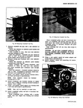
 Next
Next
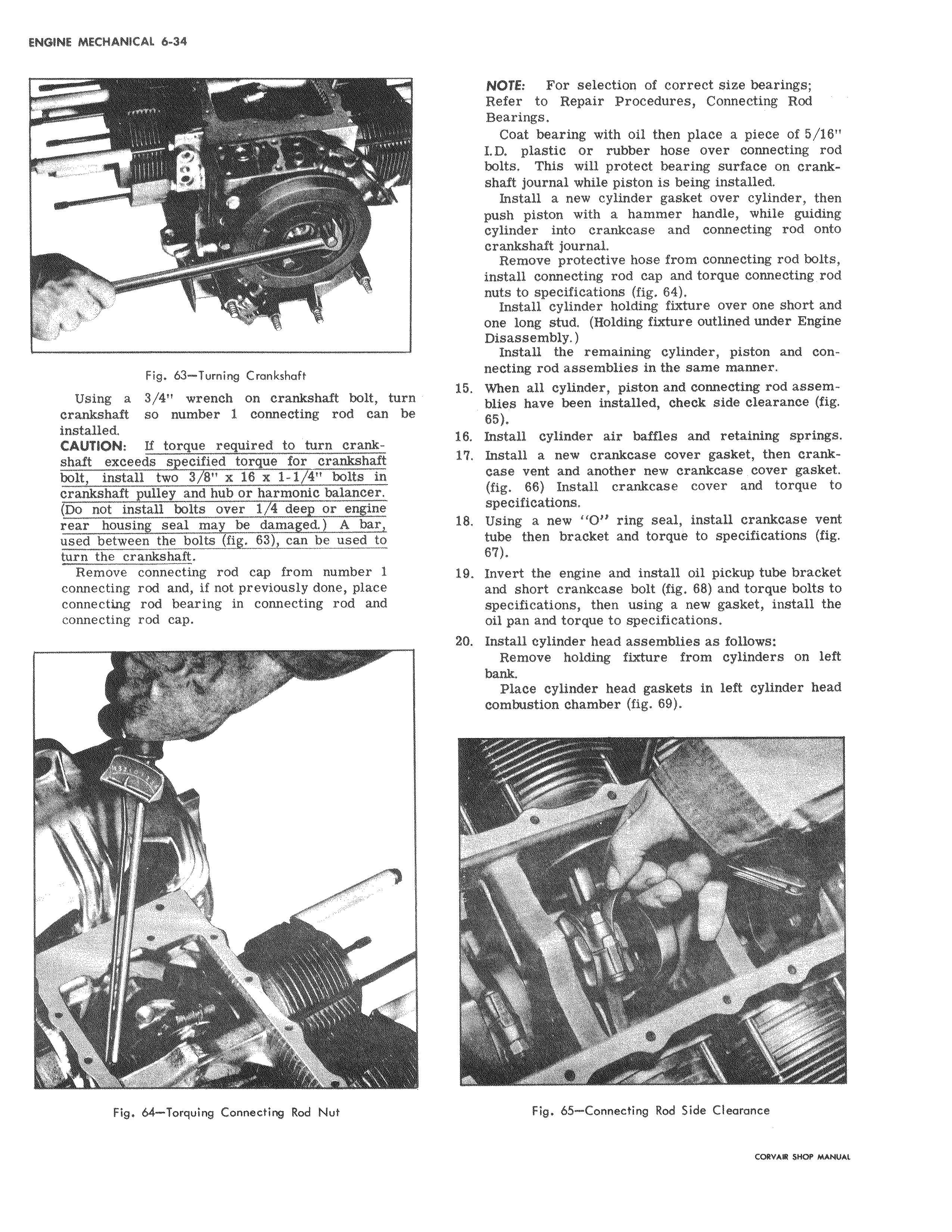
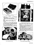
ys 4 h ll Fig 63 Turning Crankshaft Using a 3 4 wrench on crankshaft bolt turn y crankshaft so number 1 connecting rod can be installed CAUTION If torque required to turn crankshaft exceeds specified torque for crankshaft bolt install two 3 811 x 16 x 1 1 411 bolts in crankshaft pulley and hub or harmonic balancer Do not install bolts over 1 4 deep or engine rear housing seal may be damaged A bar used between the bolts fig 63 can be used to turn the crankshaft Remove connecting rod cap from number 1 connecting rod and if not previously done place connecting rod bearing in connecting rod and connecting rod cap f a Fig 64 Torquing Connecting Rod Nut NOT9 For selection of correct size bearings Refe to Repair Procedures Connecting Rod Bearings Co t bearing with oil then place a piece of 5 18 LD plastic or rubber hose over connecting rod bolts This will protect bearing surface on crankshaft l journal while piston is being installed Ins kall a new cylinder gasket over cylinder then push f piston with a hammer handle while guiding cylin er into crankcase and connecting rod onto crankshaft journal Remove protective hose from connecting rod bolts install connecting rod Cap and torque connecting rod nuts to specifications fig 64 Install cylinder holding fixture over one short and one long stud Holding fixture outlined under Engine Disa4sembly Indtall the remaining cylinder piston and connectihg rod assemblies in the same manner 15 When all cylinder piston and connecting rod assemblies4 have been installed check side clearance fig 65 18 install cylinder air baffles and retaining springs 1 Install a new crankcase cover gasket then crank case vent and another new crankcase cover gasket fig 66 Install crankcase cover and torque to specifications 18 Using a new O ring seal install crankcase vent tube then bracket and torque to specifications fig 6 19 Inve1 t the engine and install oil pickup tube bracket and short crankcase bolt fig 68 and torque bolts to specifications then using a new gasket install the oil pan and torque to specifications 20 Installl cylinder head assemblies as follows Remove holding fixture from cylinders on left bank Place cylinder head gaskets in left cylinder head combustion chamber fig 69 II t i Fig 65 Connecting Rod Side Clearance coRVAw srror MANUAL