Jeep Parts Wiki | Ford Parts Wiki
Home | Search | Browse
|
Corvair Chassis Shop Manual December 1964 |
|
Prev
 Next
Next
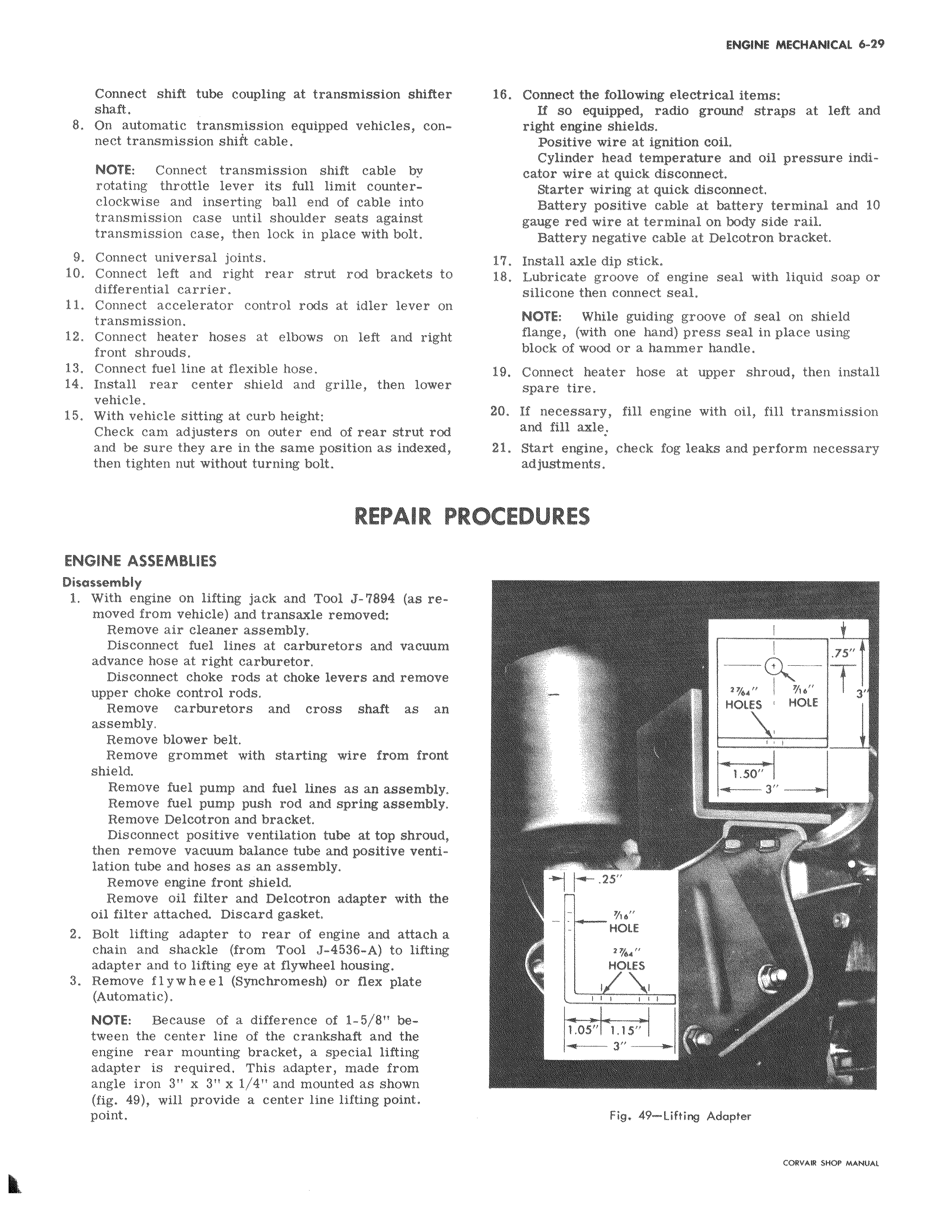
Connect shift tube coupling at transmission shifter shaft 8 On automatic transmission equipped vehicles connect transmission shift cable NOTE Connect transmission shift cable by rotating throttle lever its full limit counterclockwise and inserting ball end of cable into transmission case until shoulder seats against transmission case then lock in place with bolt 9 Connect universal joints 10 Connect left and right rear strut rod brackets to differential carrier 11 Connect accelerator control rods at idler lever on transmission 12 Connect heater hoses at elbows on left and right front shrouds 13 Connect fuel line at flexible hose 14 Install rear center shield and grille then lower vehicle 15 With vehicle sitting at curb height Check cam adjusters on outer end of rear strut rod and be sure they are in the same position as indexed then tighten nut without turning bolt REPAIR F ENGINE ASSEMBLIES Disassembly 1 With engine on lifting jack and Tool J 7894 as removed from vehicle and transaxle removed Remove air cleaner assembly Disconnect fuel lines at carburetors and vacuum advance hose at right carburetor Disconnect choke rods at choke levers and remove upper choke control rods Remove carburetors and cross shaft as an assembly Remove blower belt Remove grommet with starting wire from front shield Remove fuel pump and fuel lines as an assembly Remove fuel pump push rod and spring assembly Remove Delcotron and bracket Disconnect positive ventilation tube at top shroud then remove vacuum balance tube and positive ventilation tube and hoses as an assembly Remove engine front shield Remove oil filter and Delcotron adapter with the oil filter attached Discard gasket 2 Bolt lifting adapter to rear of engine and attach a chain and shackle from Tool J 4536 A to lifting adapter and to lifting eye at flywheel housing 3 Remove flywheel Synchromesh or flex plate Automatic NOTE Because of a difference of 1 5 8 between the center line of the crankshaft and the engine rear mounting bracket a special lifting adapter is required This adapter made from angle iron 3 x 3 x 1 4 and mounted as shown fig 49 will provide a center line lifting point point 16 Connect the following electrical items If so equipped radio ground straps at left and right engine shields Positive wire at ignition coil Cylinder head temperature and oil pressure indicator wire at quick disconnect Starter wiring at quick disconnect Battery positive cable at battery terminal and 10 gauge red wire at terminal on body side rail Battery negative cable at Delcotron bracket 17 Install axle dip stick 18 Lubricate groove of engine seal with liquid soap or silicone then connect seal NOTE While guiding groove of seal on shield flange with one hand press seal in place using block of wood or a hammer handle 19 Connect heater hose at upper shroud then install spare tire 20 If necessary fill engine with oil fill transmission and fill axle 21 Start engine check fog leaks and perform necessary adjustments ROCEDURES I 75 3 HOLES HOLE 1 50 m 31 25 HOLE z HOLES I I w w L A 1 1 05 1 15 1 Fig 49 Liftirg Adapter