Jeep Parts Wiki | Ford Parts Wiki
Home | Search | Browse
|
Corvair Chassis Shop Manual December 1964 |
|
Prev

 Next
Next
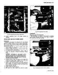
VALVE SPRINGS AND OR VALVE STEM OIL SEALS NOTE Intake valves on all Corvair engines are provided with valve stem oil seals Valve springs and or valve stem oil seals can be re placed with the cylinder head installed Replacement 1 Remove the spark plug valve rocker cover rock r arm nut rocker arm ball rocker arm and push rod on the cylinder to be serviced 2 Apply compressed air to the spark plug hole to hold the valve in place NOTE A tool to apply air to the cylinder is available through local jobbers or may be manufactured fig 37 3 Using Tool J 5892 to compress the valve spri remove the valve locks valve cap and valve spring and damper assembly 4 If valve stem oil seal on intake valve is to be r placed remove seal from valve guide 5 Check valve spring installed height as follows Install the spring cap and valve locks without the spring Hold the spring cap and pull the valve against the seat then measure the distance between spring cap and spring seat fig 38 i NOTE This locates the spring cap in the installed position 6 Remove valve locks and spring cap and if necessary shim spring NOTE Spring shims are available in 030 thickness Do not shim if shim will bring installed height below minimum specification 7 On intake valves install new valve stem oil seal using special plastic protector sleeve to prevent seal damage as seal passes over the valve lock grooves Push seal on guide until it bottoms n guide end 8 Place the valve spring and damper assembly a d valve cap in place fr UI Fig 37 Air Adapter Tool I Fig 38 Measuring Valve Spring Installed Height 9 Compress the valve spring with Tool J 5892 and install valve cap and valve locks then release the compressor tool making sure the lock seats properly NOTE Grease may be used to hold the locks in place while releasing the compressor tool 10 Install spark plug with a new gasket then install valve rocker arm rocker arm ball and rocker arm nut and adjust valve as outlined under Valve Lifters 11 Using a new gasket install the valve rocker cover and torque to specifications CONNECTING ROD BEARINGS Replacement 1 Remove upper shroud and crankcase cover as outlined 2 Position connecting rod for removal of cap 3 Remove connecting rod nuts then remove connecting rod cap 4 Install a piece of 5 16 LD plastic or rubber hose on connecting rod bolt to protect crankshaft journals fig 39 5 Remove spark plug from cylinder being serviced and position connecting rod so bearing may be removed 6 Remove bearing from connecting rod and connecting rod cap NOTE Refer to Repair Procedures Connecting Rod Bearing for clearances and bearing selection 7 Lubricate and install bearing in connecting rod and connecting rod cap 8 Install connecting rod cap and torque t o specifications 8 Install spark plug with a new gasket and torque to specifications

 Next
Next