Jeep Parts Wiki | Ford Parts Wiki
Home | Search | Browse
|
Corvair Chassis Shop Manual December 1964 |
|
Prev

 Next
Next
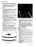
i E y Fig 35 Push Rods Installed Oil cooler left cylinder head Muffler muffler shield and muffler hanger right cylinder head Spark plugs and vacuum balance tube hose at cylinder head Bolts attaching upper shroud to front and rear shrouds and bolts attaching front and rear shrouds to cylinder head Exhaust manifolds NOTE On left rear shroud it will be necessary to disconnect heater hose at elbow to gain access to one bolt 4 On the right cylinder head disconnect wire to cylinder head temperature sending unit 5 Remove cylinder head assembly as follows Remove valve rocker arm cover and discard gasket Remove rocker arm nuts rocker arm balls rocker arms and push rods Place in a rack so they may be installed in their original location Remove rocker arm studs and push rod guides then remove and discard rocker arm stud O ring seals Pull push rod tubes from crankcase bore and remove and discard inner O ring seal then remove push rod tube from cylinder head and remove and discard O ring seal Remove cylinder head nuts then remove cylinder head assembly from crankcase studs and discard cylinder head gaskets Installation 1 Install cylinder head assembly as follows Place cylinder head gasket in cylinder head combustion chamber Install cylinder head assembly over studs and carefully guide into place Install 6 cylinder head nuts finger tight Install new O ring seals lightly coated with oil on long end of push rod tubes then install push rod tubes through bore in cylinder head and install new O ring seals lightly coated with oil on inner end of push rod tubes Start push rod tubes into bores in cylinder head and crankcase then seat the push rod tubes with a 9 16 deep socket placed against cylinder head end of push rod tube and tapped lightly with a hammer Install new O ring seals lightly coated with oil into rocker arm stud bore in cylinder head Install push rod guides then rocker arm studs finger tight Torque cylinder head nuts and rocker arm studs a little at a time in the sequence shown fig 34 until the specified torque is reached Install push rods with the side oil hole out Install rocker arms rocker arm balls and rocker arm nuts NOTE Whenever new rocker arms or rocker arm balls are installed coat surfaces lightly with Molykote or its equivalent 2 Connect wire to cylinder head temperature sending unit on right cylinder head 3 Adjust valves as outlined under Valve Lifters 4 Using a new gasket install valve rocker cover and torque to specifications 5 install the following items as outlined Exhaust manifold Bolts attaching front and rear shroud to cylinder head and bolts attaching upper shroud to front and rear shroud Spark plugs and vacuum balance tube hose Muffler hanger muffler heat shield and muffler right cylinder head Oil cooler left cylinder head Exhaust duct lower shroud and side shield Ignition coil and bracket right cylinder head Carburetor mounting studs carburetor and choke control rods 6 Fill with oil then connect battery positive cable 7 Synchronize carburetors as outlined in Engine Tune up 8 Check for oil leaks 9 Install air cleaner assembly and spare tire rF s rsr d a Fig 36 Rocker Arm Cover Installed

 Next
Next