Jeep Parts Wiki | Ford Parts Wiki
Home | Search | Browse
|
Corvair Chassis Shop Manual December 1964 |
|
Prev

 Next
Next
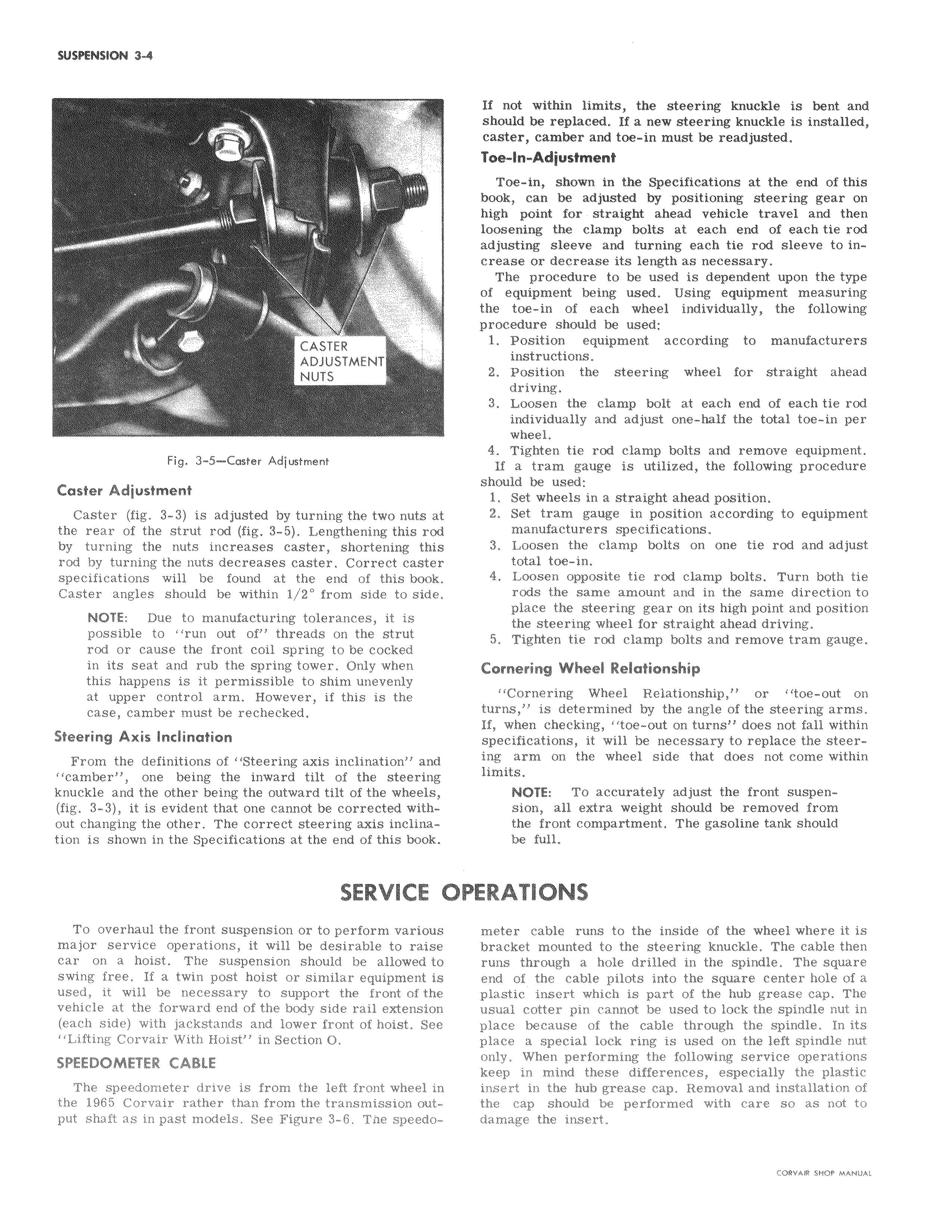
j a CASTER ADJUSTMENT NUTS Fig 3 5 Caster Adjustment Caster Adjustment Caster fig 3 3 is adjusted by turning the two nuts at the rear of the strut rod fig 3 5 Lengthening thisl rod by turning the nuts increases caster shortening Ithis rod by turning the nuts decreases caster Correct caster specifications will be found at the end of this book Caster angles should be within 1 2 from side to side NOTE Due to manufacturing tolerances it is possible to run out of threads on the strut rod or cause the front coil spring to be cockedl in its seat and rub the spring tower Only when this happens is it permissible to shim unevenlyl at upper control arm However if this is the I case camber must be rechecked Steering Axis Inclination From the definitions of Steering axis inclination a camber one being the inward tilt of the steelring knuckle and the other being the outward tilt of the wheels fig 3 3 it is evident that one cannot be corrected thout changing the other The correct steering axis inc nation is shown in the Specifications at the end of this book SERVICE C To overhaul the front suspension or to perform va ous major service operations it will be desirable to aise car on a hoist The suspension should be allowed to swing free If a twin post hoist or similar equipment is used it will be necessary to support the front f the vehicle at the forward end of the body side rail extension each side with jackstands and lower front of hoist See Lifting Corvair With Hoist in Section O SPEEDOMETER CABLE I The speedometer drive is from the left front wheel in the 1965 Corvair rather than from the transmission output shaft as in past models See Figure 3 6 The spiedoI If ndi within limits the steering knuckle is bent and should be replaced If a new steering knuckle is installed casteT camber and toe in must be readjusted Toe 6 Adjustment Toe in shown in the Specifications at the end of this book can be adjusted by positioning steering gear on high point for straight ahead vehicle travel and then looseging the clamp bolts at each end of each tie rod adjusting sleeve and turning each tie rod sleeve to increase or decrease its length as necessary The procedure to be used is dependent upon the type of equipment being used Using equipment measuring the toe in of each wheel individually the following procedure should be used 1 Position equipment according to manufacturers instructions 2 Position the steering wheel for straight ahead driving 3 Loosen the clamp bolt at each end of each tie rod individually and adjust one half the total toe in per wheel 4 Tighten tie rod clamp bolts and remove equipment If a tram gauge is utilized the following procedure should be used 1 Set wheels in a straight ahead position 2 Set tram gauge in position according to equipment manufacturers specifications 3 Loosen the clamp bolts on one tie rod and adjust total toe in 4 Loosen opposite tie rod clamp bolts Turn both tie rods the same amount and in the same direction to place the steering gear on its high point and position the steering wheel for straight ahead driving 5 Tighten tie rod clamp bolts and remove tram gauge Cornering Wheel Relationship Cornering Wheel Relationship or toe out on turns is determined by the angle of the steering arms If When checking toe out on turns does not fall within specifications it will be necessary to replace the steering arm on the wheel side that does not come within limits NOTE To accurately adjust the front suspension all extra weight should be removed from the front compartment The gasoline tank should be full IPERATIONS meter cable runs to the inside of the wheel where it is bracket mounted to the steering knuckle The cable then runs through a hole drilled in the spindle The square end of the cable pilots into the square center hole of a plastic insert which is part of the hub grease cap The usuah cotter pin cannot be used to lock the spindle nut in place because of the cable through the spindle In its place a special lock ring is used on the left spindle nut only When performing the following service operations keep in mind these differences especially the plastic insek t in the hub grease cap Removal and installation of the cap should be performed with care so as not to dam age the insert

 Next
Next