Jeep Parts Wiki | Ford Parts Wiki
Home | Search | Browse
|
Corvair Chassis Shop Manual Supplement December 1967 |
|
Prev

 Next
Next
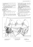
BODY AND CHASSIS ELECTRICAL I2 4 2 Connect cluster wiring harness to instrument panel wiring harness 3 Install screws retaining cluster assembly to console 4 Connect speedometer cable to rear of speedometer I gv housing connect trip odometer and speed warning I NI V if so equipped I Q It W 5 Position heater control to cluster and install retain I W I It i TI ing screws M II I I 6 Install light and wiper switch bezel retaining nuts III I Q I On Powerglide models install shift lever knob and I gy on A C models install air outlet I II A I I 7 Install mast jacket upper support clamp and lower Lr support I I I I 8 Connect battery ground cable and check operation of I cluster assembly I DIRECTIONAI SIGNAL SWITCH Fig 7 WQAYLI The directional signal switch assembly includes as V integral components a hazard warning switch and a lane changer feature Components of the assembly except for the cancelling and detent springs are not serviceable and W I I I I the complete switch assembly must be replaced if a mal functmn Should Occur Flg 8 Dnrechon I Sngnol Swatch AssembIy R m V I SI d r I GMI T I pI g C I m 7 Remove mast jacket trim cover assembly II DISCONIQCI battery gmund ab1 I 8 Remove retaining ring and steering shaft upper wave 2 Disconnect directional signal multiple connectorfrom and thrust WaSh rS chassis harness connector under instrument panel 9 Cut harness near Connector 3 Remove steering wheel assembly as described in 10 LOOSBH mastjackgt upper Support bolts 4 ESQIIOH 9 St grmg Of tm mgnualf d d t 1 11 Remove three switch mounting screws slide com Ihg uppgr Sarmg pm O3 Sprmg an Imc mm plete assembly from mast jacket and steering shaft signal cancelling cam from upper steering shaft 12 Remove Wire protector Cup and Or Cover 5 Remove directional signal lever screw and lever I 6 Push in hazard warning switch knob unscrew and InSt II ti n remove knob 1 Position directional switch assembly on bearing I gg I Q I HAZARD WARNING CANCELLING I SWITCHES I SPRINGS as I I U if I s s I kI II I 4 s 4 1 I ZZI I IIIIIII It I I IIIII I I I er I J i r I I I I I rrvl v I I I jr I I lj I I Ii I I I I I I l ft S22 rll I llce V II I J ltcc Vgar l I I I I I l I I It I I I I 2 I I TN I DETENT I II I I I spmwos n I Fig 7 DIrectI0n I SIgr1 I Switch CORVAIR SHOP MANUAL SUPPLEMENT

 Next
Next