Jeep Parts Wiki | Ford Parts Wiki
Home | Search | Browse | Marketplace | Messages | FAQ | Guest
|
Corvair Chassis Shop Manual Supplement December 1967 |
|
Prev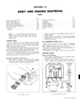
 Next
Next
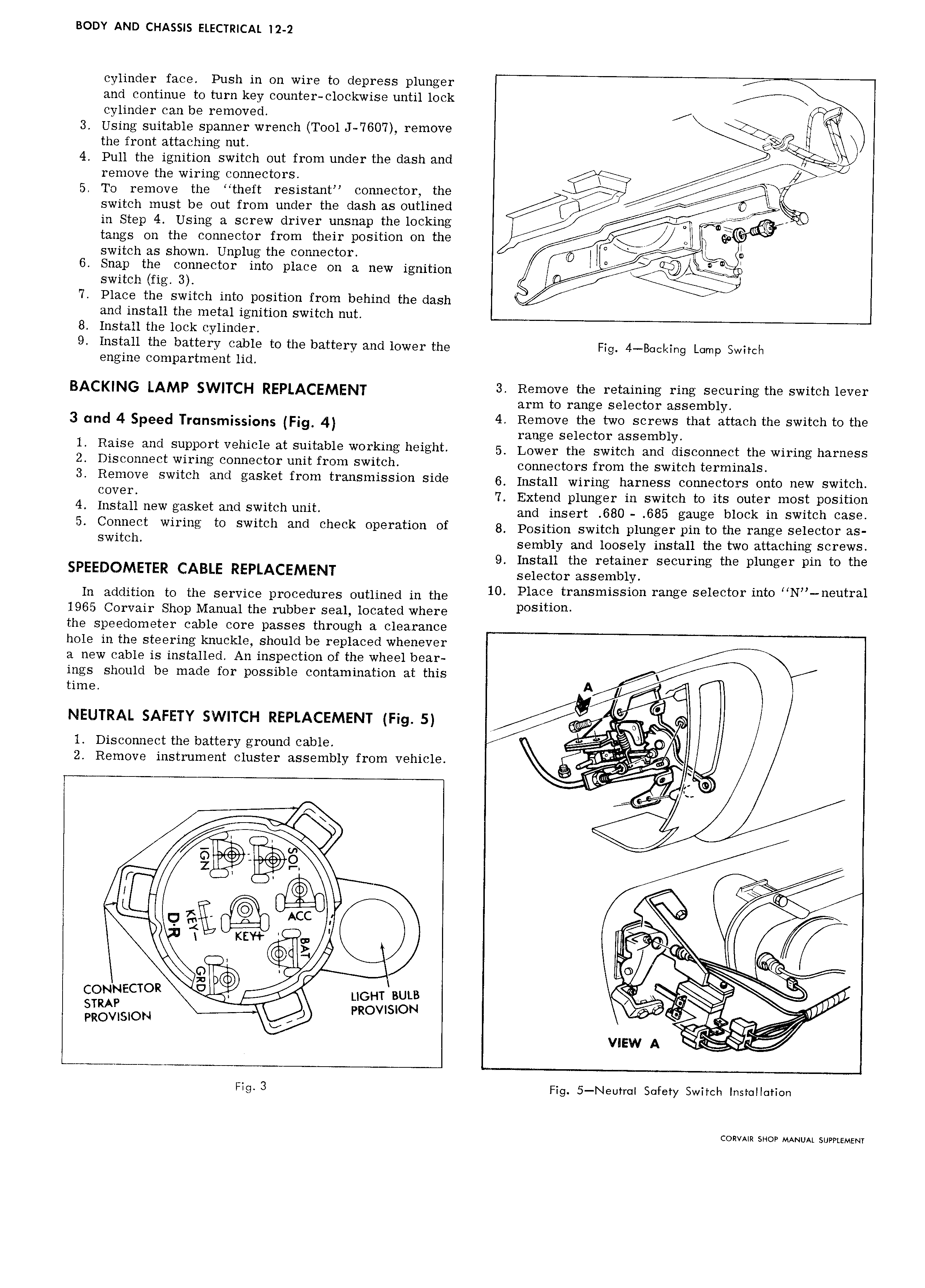
Boov AND CHASSIS ELECTRICAL 12 2 cylinder face Push in on wire to depress plunger and continue to turn key counter clockwise until lock F cylinder can be removed 3 Using suitable spanner wrench Tool J 7607 remove the front attaching nut 4 Pull the ignition switch out from under the dash and remove the wiring connectors V1 xy 5 To remove the theft resistant connector the X P switch must be out from under the dash as outlined 97 Vx in Step 4 Using a screw driver unsnap the locking Q tangs on the connector from their position on the Z i switch as shown Unplug the connector i i D s O Q 6 Snap the connector into place on a new ignition F switch fig 3 7 Place the switch into position from behind the dash and install the metal ignition switch nut 8 Install the lock cylinder 9 Install the battery cable to the battery and lower the Fig 4 B cking Lump Switch engine compartment lid BAC N AMp SWHCH REPLACEMENT 3 Remove the retaining ring securing the switch lever arm to range selector assembly 3 und 4 Speed Transmissions Fig 4 4 Remove the two screws that attach the switch to the I range selector assembly 1 Raise end SnPPOYtVen1c1e at Suitable workme hcighh 5 Lower the switch and disconnect the wiring harness 2 Disconnect wiring connector unit from switch Connggtgrs from hs switch 1 s ymma s 3 Remeve Switch end gasket fren Fnensnnssien Side 6 Install wiring harness connectors onto new switch ccVeT 7 Extend plunger in switch to its outer most position 4 I St 11 new gasket wd Switch mit and insert 680 685 gauge bimk in switch me 5 Ccnnect Wiring tc Switch and check Opel UGH of 8 Position switch plunger pin to the range selector as Switch sembly and loosely install the two attaching screws 9 Install the retainer securing the plunger pin to the SPEEDOMETER CABLE REPLACEMENT Sglggtgr assembly In addition to the service procedures outlined in the 10 Phe transmission range Selector me HN n utra1 1965 Corvair Shop Manual the rubber seal located where p S1t1 n the speedometer cable core passes through a clearance hole in the steering knuckle should be replaced whenever a new cable is installed An inspection of the wheel bear ings should be made for possible contamination at this time A M NEUTRAL SAFETY SWITCH REPLACEMENT Fig 5 i w ra Yg 1 Disconnect the battery ground cable 0 2 Remove instrument cluster assembly from vehicle i i i i g F L V E x g fi ACC s P Z x r x K F QF ec la ei cowmacion I LIGHT BULB 1 STRAP pRovnsL0N e is W PROVISION A 1i as view A Fig 3 Fig 5 Neutr I Sotety Switch Installation CORVAIR SHOP MANUAL SUPPLEMENT