Jeep Parts Wiki | Ford Parts Wiki
Home | Search | Browse
|
Corvair Chassis Shop Manual Supplement December 1967 |
|
Prev

 Next
Next
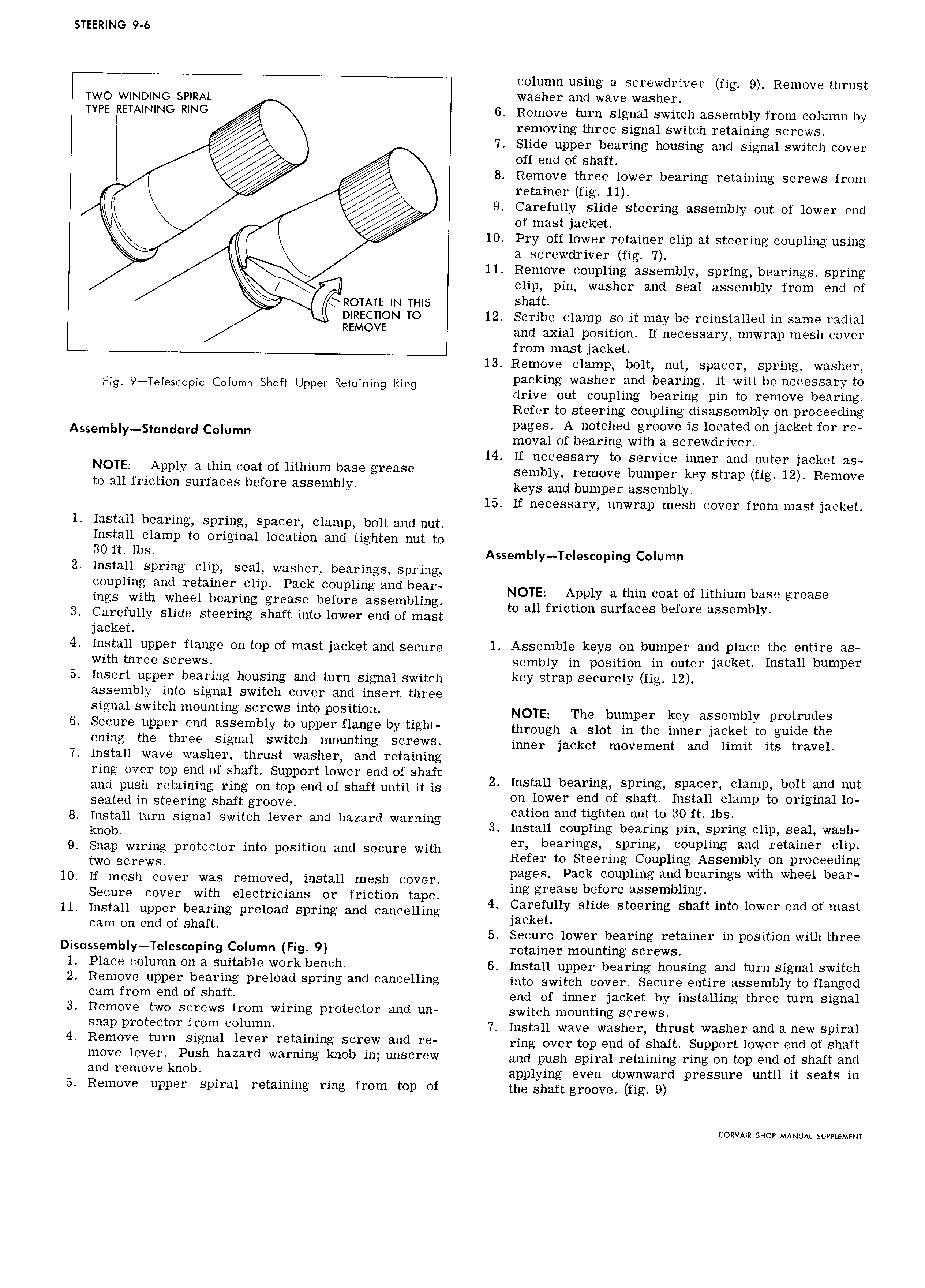
STEERING 9 6 column using a screwdriver fig 9 Remove thrust TWO WINDING SPIRAL washer and wave washer TYPE RETAINING RING 6 Remove turn signal switch assembly from column by removing three signal switch retaining screws 7 Slide upper bearing housing and signal switch cover off end of shaft 8 Remove three lower bearing retaining SCFGWS fI O1 fl retainer fig 11 9 Carefully slide steering assembly out of lower end of mast jacket m 10 Pry off lower retainer clip at steering coupling using Q a screwdriver fig 7 11 Remove coupling assembly spring bearings spring clip pin washer and seal assembly from end of Q RoTATE IN THIS Shaft DlRECTlON TO 12 Scribe clamp so it may be reinstalled in same radial REMOVE and axial position If necessary unwrap mesh cover from mast jacket 13 Remove clamp bolt nut spacer spring washer Fig 9 Telescopic Column Shaft Upper Retoining Ring paeklng Washer land b 3 r 1ng lt wlu be necessary to drive out coupling bearing pin to remove bearing Refer to steering coupling disassembly on proceeding Aeem Y e Comme 551 e nZZE Z dwitE CZZ Z EZi pmt fm 14 If necessary to service inner and outer jacket as NOTE ApplY 3 iliiil eeel ef lithium heee gre3 Se sembly remove bumper key strap fig 12 Remove to all friction surfaces before assembly keys and bumper e ssembiy 15 If necessary unwrap mesh cover from mast jacket 1 Install bearing spring spacer clamp bolt and nut Install clamp to original location and tighten nut to 30 it lbs Assembly Telescoping Column 2 Install spring clip seal washer bearings spring g 1ii i h ei i i ipe 2i J E Li Z2 Ei i Nele eeee e the eee ef me eee ee eas 3 Carefully slide steering shaft into lower end of mast to all fmctwn surfaces before assembly jacket 4 Install upper flange on top of mast jacket and secure l Assemble l eYS Oli bumper and pleee the entire es with three screws sembly in position in outer jacket Install bumper 5 Insert upper bearing housing and turn signal switch key Strap Securely fig lz assembly into signal switch cover and insert three signal switch mounting screws into position NOTE The bumper key assembly protrudgs 6 Seeure upper end assembly fe upper flange by tight through e Sint in the inner jacket to guide the eulhg the three eieuel ewiteh meuhfihg Screws inner jacket movement and limit ite travel 7 Install wave washer thrust washer and retaining ring over top end of shaft Support lower end of shaft and push retaining ring on top end of shaft until it is 2 Install b armg sprmg Spawn C1amp boll and nut Scyted in Steering Shaft groove on lower end of shaft Install clamp to original lo 8 Install turn signal switch lever and hazard warning eeeee and tighten nut tO 30 ft lbs knOb 3 Install coupling bearing pin spring clip seal wash 9 Snap wiring protector into position and secure with 9r b 3 rmgs Sprmg Fouplmg and retainer C1 1p two Screws Refer to Steering Coupling Assembly on proceeding 10 If mesh cover was removed install mesh cover Pages Peck O p11 ee dl e eS wlth Wheel bear Secure cover with electricians or friction tape mg grease before ass mbhng 11 Install upper bearing pmload Spring and cancelling 4 Carefully slide steering shaft into lower end of mast cam on end of shaft Jacket 5 Secure lower bearing retainer in position with three Dis ssemb y TeIescoping Column Fig 9 retainer mounting screws l Place 0ll1l Oh 3 Suitable W01 k befleh 6 Install upper bearing housing and turn signal switch 2 Remel e upper bearing prelead Spring elld eelleelllrlg into switch cover Secure entire assembly to flanged Cam f1 0m elld of Sh fil end of inner jacket by installing three turn signal 3 Remove two screws from wiring protector and un switch mounting Screws SMP Pr0teeii0r fl 0 l 0lumll 7 Install wave washer thrust washer and a new spiral 4 Remeve tum Sighel lever reteiuiug Screw and re ring over top end of shaft Support lower end of shaft n lOV lever P1 1Sh h3Z8 I d warning knob in UHSCTQW and push Spiral retaining ring on top end of shaft and aud remeve l eb applying even downward pressure until it seats in 5 Remove upper spiral retaining ring from top of the shaft groove fig 9 CORVAIR SHOP MANUAL SUPPLEMENT

 Next
Next