Jeep Parts Wiki | Ford Parts Wiki
Home | Search | Browse
|
Corvair Chassis Shop Manual Supplement December 1967 |
|
Prev

 Next
Next
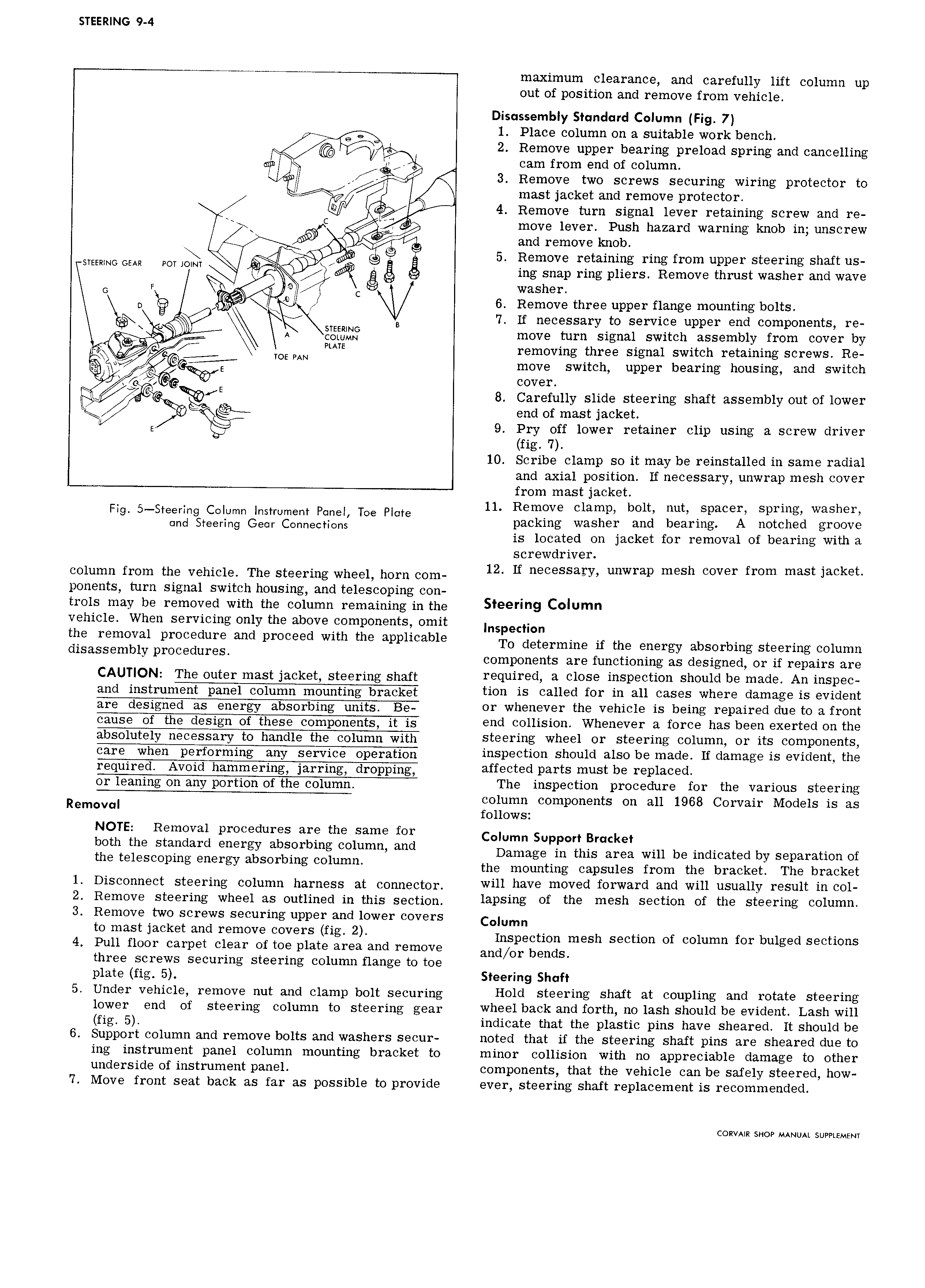
STEERING 9 4 maximum clearance and carefully lift column up out of position and remove from vehicle Disassembly Standard Column Fig 7 f Q l Place column on a suitable work bench 6 9 2 Remove upper bearing preload spring and cancelling nf cam from end of column A 3 Remove two screws securing wiring protector to A mast jacket and remove protector tz W 4 Remove turn signal lever retaining screw and re C f Y move lever Push hazard warning knob in unscrew e Nur and remove knob Aw Q 5 Remove retaining ring from upper steering shaft us STEEWNG Gm POT JOM w 5 ing snap ring pliers Remove thrust washer and wave G F C washer l D lg gg 6 Remove three upper flange mounting bolts B 7 If necessary to service upper end components re R A move turn signal switch assembly from cover by I MTE removing three signal switch retaining screws Re xel Y t TOEPAN move switch upper bearing housing and switch l 2 E cover E if Q E 8 Carefully slide steering shaft assembly out of lower l e 5 end of mast jacket E 9 Pry off lower retainer clip using a screw driver fig 7 10 Scribe clamp so it may be reinstalled in same radial and axial position lf necessary unwrap mesh cover from mast jacket 11 Remove clamp bolt nut spacer spring washer Flgl 5 eslezeruinggtelenrliewnggnClezlfu lsierlegilllitil Toe Plate packing washer and bearing A notched groove is located on jacket for removal of bearing with a screwdriver column from the vehicle The steering wheel horn com l2 ll neCeSSe ey unwrep mesh Cover from meet leckee ponents turn signal switch housing and telescoping con trols may be removed with the column remaining in the l 9 C lUm vehicle When servicing only the above components omit Inspedion the removal procedure and proceed with the applicable TO determine if the energy absorbing Steering Column disassembly pmeeduree components are functioning as designed or if repairs are QAUT QN The enter mast jacket Steering Shaft required a close inspection should be made An inspec and instrument pane eejnmn mounting bracket tion is called for in all cases where damage is evident or whenever the vehicle is being repaired due to a front end collision Whenever a force has been exerted on the steering wheel or steering column or its components inspection should also be made If damage is evident the required Avoid hammering jarring dropping fl Ct d Parts must be Pl3 d or leaning on any portion of the column The inspection procedure for the various steering column components on all 1968 Corvair Models is as R m v renews IE h Rfmgva procedures age the same for Column Support Bracket O e S en at energy ebeer mg eelumm and Damage in this area will be indicated by separation of t 1 S Pmg energy absorbing Comme the mounting capsules from the bracket The bracket 1 Disconnect steering column harness at connector will hal m0V u lurwaru and Wlll usually result ln Cul 2 Remove steering wheel as outlined in this section lapslng of the mesh S CtlOll Ol the Sleerlug Culumll 3 Remove two screws securing upper and lower covers Column te meet leeket and remove eevere fig 2 Inspection mesh section of column for bulged sections 4 Pull floor carpet clear of toe plate area and remove and OI bends three screws securing steering column flange to toe plate fig 5 Steering Shaft 5 Under vehicle remove nut and clamp bolt securing Hold steering shaft at coupling and rotate steering lower end of steering eelumn tg steering gear wheel back and fOI th HO lash ShOLlICl be evidellf Lash will f1g 5 indicate that the plastic pins have sheared It should be 6 Support column and remove bolts and washers secur noted that if the steering shaft pins are sheared due to ing instrument panel column mounting bracket to minor collision with no appreciable damage to other underside of instrument panel components that the vehicle can be safely steered how 7 Move front seat back as far as possible to provide ever steering shaft replacement is recommended CORVAIR SHOP MANUAL SUPPLEMENT

 Next
Next