Jeep Parts Wiki | Ford Parts Wiki
Home | Search | Browse | Marketplace | Messages | FAQ | Guest
|
Corvair Chassis Shop Manual Supplement December 1967 |
|
Prev

 Next
Next
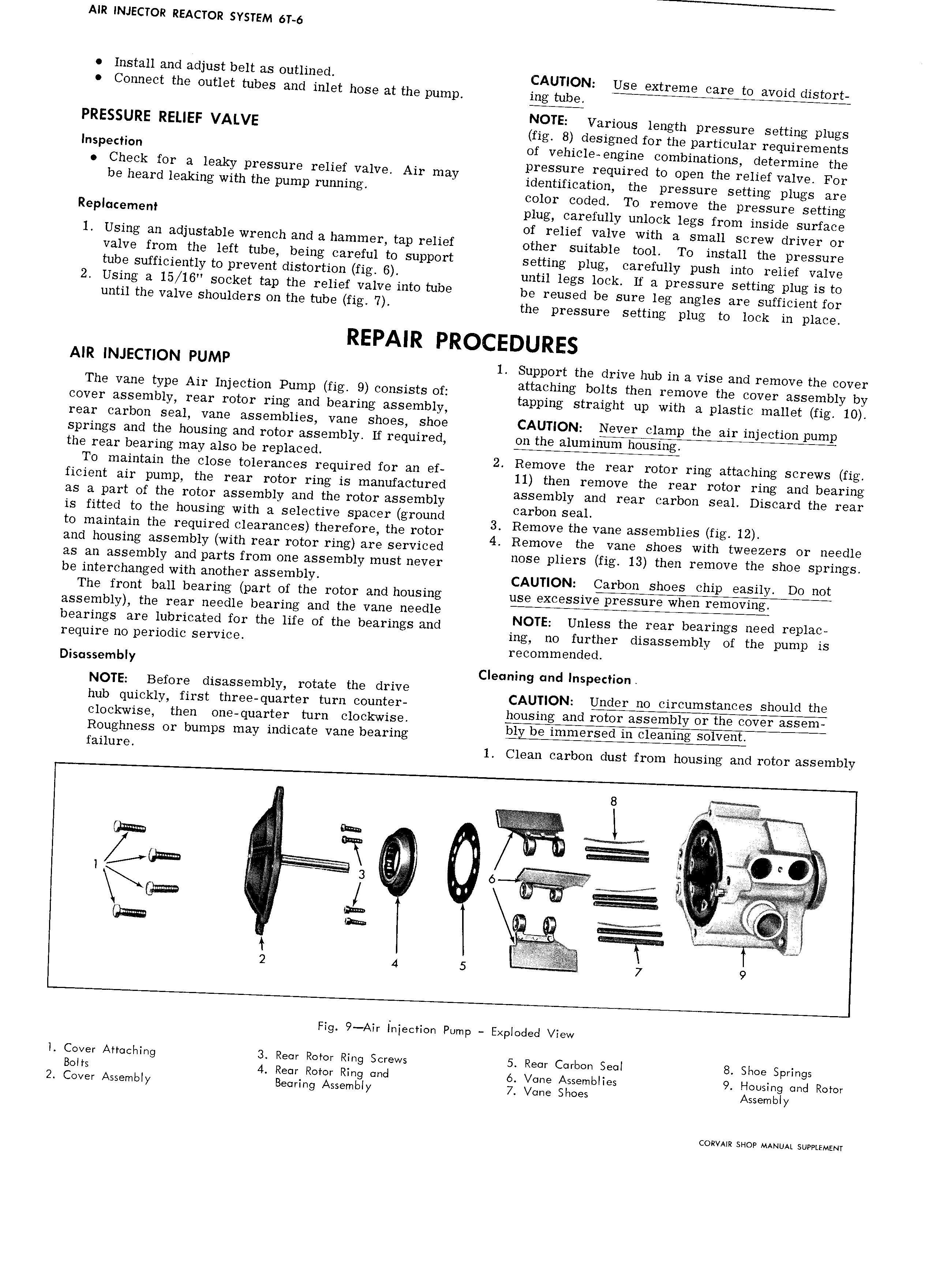
AIR INJECTOR REACTOR SYSTEM 6T 6 Install and adjust belt as outlined CAUTION Use extreme care to avoid distort C0I 1H9Ct the OI IIZIGIZ tubes and lfll t h S9 at fhg pump jug NOTE Various length pressure setting plugs PRESSURE RELIEF VALVE fig 8 designed for the particular requirements lnspedion of vehicle engine combinations determine the Check for a leaky pressure relief valve Air may Pggsigre required to Open the r 1 i fVa1V For be heard leaking with the pump rmmmgl 1 en 1 icatlon the pressure setting plugs are color coded To remove the pressure setting Replccemem plug Icagefullly unlgik legs from inside surface 0 re ie va ve wi a small screw driver or 1 Using an dj St3 bI W1 h and 3 hammer tap P li f other suitable tool To install the pressure valve from the left tube being careful to support setting plug carefully push into relief valve tube sufficiently to prevent distortion fig 6 until legs lock If a pressure setting plug is to 2 Using a 15 16 socket tap the relief valve into tube bg rgusgd bg sure leg angles are Sufficient Ol until the valve shoulders on the tube fig 7 the pressure setting plug to lock in place AIR INJECTION PUMP 1 Support the drive hub in a vise and remove the cover The vane type Air Injection Pump fig 9 consists of igtaghmg tboititthem rgfgove Shetwvwiaiseyblylgy cover assembly rear rotor ring and bearing assembly ppmg S mug up wr a P as rc ma E lg rear carbon seal vane assemblies vane shoes shoe CAUTION Never clamp the air injection pump springs and the housing and rotor assembly If required on the aluminum housing the rear bearing may also be replaced 2 Remove the rear rotor ring attaching screws fig To maintain the close tolerances required for an ef 11 then remove the rear rotor rm and b arm ficient air pump the rear rotor ring is manufactured assembl and mar Carbon Seal Disiard the rea as a part of the rotor assembly and the rotor assembly Garbo SLM is fitted to the housing with a selective spacer ground 3 R moge the ang assemblies fi 12 to maintain the required clearances therefore the rotor 4 Remove the Va 9 Shoes Withgiwg zgrs Or needle and housing assembly with rear rotor ring are serviced HOSE Hers fi H13 then remove the Shoe S rm S as an assembly and parts from one assembly must never p g p g be interchanged with another assembly CAUTION Carbon shoes chip easily Do not The front ball bearing part of the rotor and housing use excessive pressure when removing assembly the rear needle bearing and the vane needle NOTE Unless the rear bearings need replac bearlngs are lgggcgglexdiggr the life of the bearings and mg HO further disassembly Of the pump is rrqurrr perr recommended Dlsqssembly Cleaning cmd Inspection NOTE Before disassembly rotate the drive CAUTION Under no circumstances should the hub q rr rrrsr rhr q r rr r rrrr t r hddsdg ddd clockwise then one quarter turn clockwise B Rgughness or bumps may iI1dlC3 t9 V3 I1 b 3 I iHg failure 1 Clean carbon dust from housing and rotor assembly Ei Q EIE I M r r htm ii D I Z E 3 6 M 23 i J zz gm gl V V ygyh Fig 9 Air Injection Pump Expioded View I Cover Attoching 3 Reor Rotor Ring Screws 5 Reor Carbon Seoi 8 Shoe Springs Bolts 4 Reor Rotor Ring ond 6 Vone Assembiies 9 Housing ond Rotor 2 Cover Assembiy Beoring Assembiy 7 Vone Shoes Assembiy CORVAIR SHOP MANUAL SUPPLEMENT

 Next
Next