Jeep Parts Wiki | Ford Parts Wiki
Home | Search | Browse
|
Corvair Chassis Shop Manual Supplement December 1967 |
|
Prev

 Next
Next
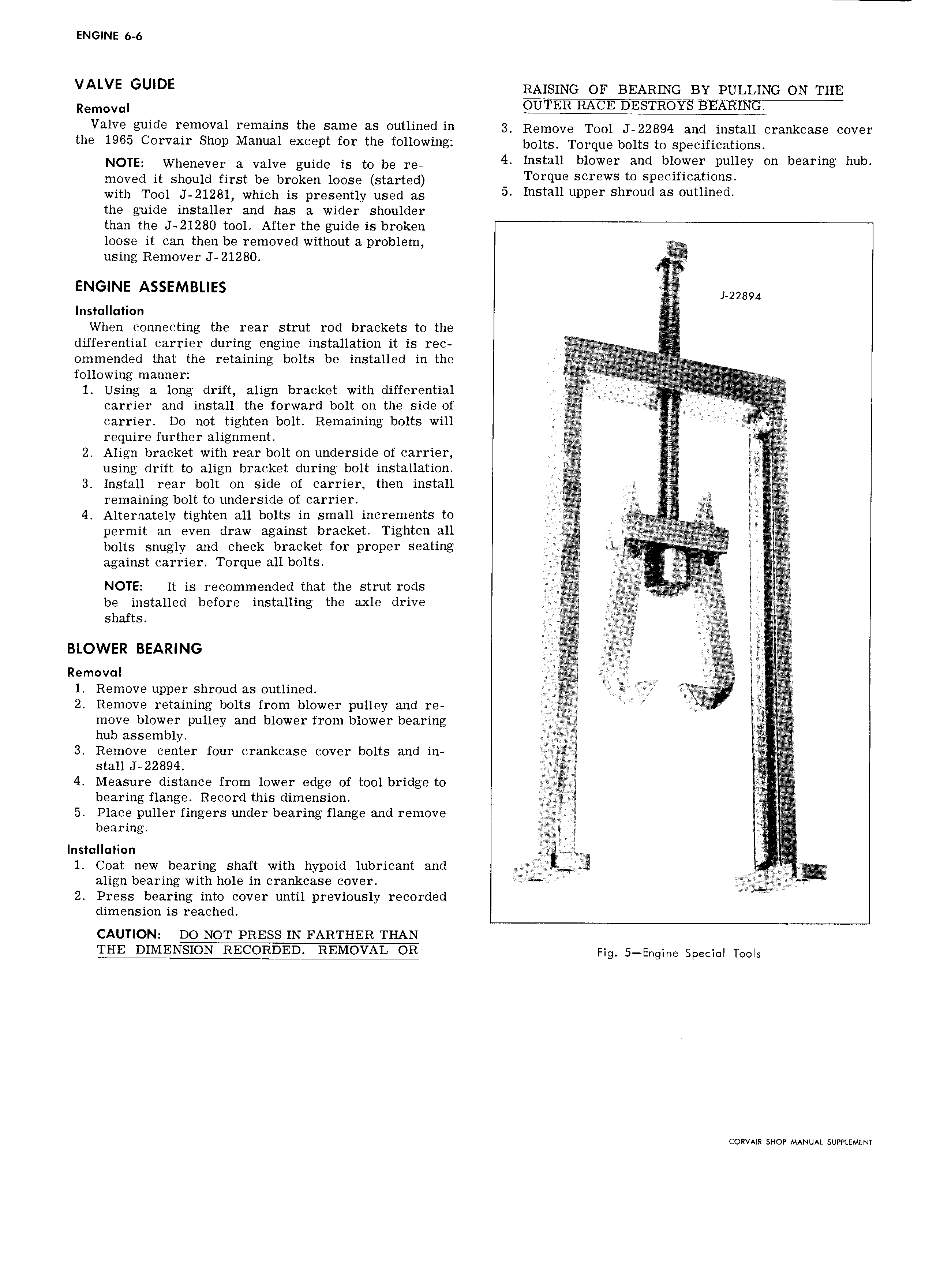
ENGINE 6 6 VALVE GUIDE RAISING or BEARING BY 1 uLL1No ON THE Removal YTER RACE DESTROYS BEARING Valva guide removal remains the same as outlined in 2 Remove Tool J 22894 and mstaii erenkease cover the 1965 Corvair Shop Manual except for the following bO1ts TO1 qug bglts to Sp CificatiOnS NOTE Whenever a Valve guide is to be I 4 Install blower and blower pulley on bearing hub moved it should first be broken loose started Tarqua Scrgws to Sp9Cifi atlOnS with Tool J 21281 which is presently used as 5 Install upper Shroud as Outlmed the guide installer and has a wider shoulder than the J 2128O tool After the guide is broken loose it can then be removed without a problem using Remover J 21280 ENGINE ASSEMBLIES 22894 Installation When connecting the rear strut rod brackets to the A differential carrier during engine installation it is rec ommended that the retaining bolts be installed in the l f ii Wi a ma ar iil 1 Using a long drift align bracket with differential carrier and install the forward bolt on the side of A I carrier Do not tighten bolt Remaining bolts will require further alignment 3 Z Align bracket with rear bolt on underside of carrier E using drift to align bracket during bolt installation gg 3 Install rear bolt on side of carrier then install V2 V remaining bolt to underside of carrier 4 Alternately tighten all bolts in small increments to AIV permit an even draw against bracket Tighten all bolts snugly and check bracket for proper seating against carrier Torque all bolts f l NOTE lt is recommended that the strut rods be installed before installing the axle drive l Shafts A 2 i Biowen BEARING Ram v 1 1 Remove l1pp I ShI O1 1d as ut1j ngd i K 2 Remove retaining bolts from blower pulley and re i move blower pulley and blower from blower bearing I hub assembly Q 3 Remove center four crankcase cover bolts and in ste11J 22894 ri 4 Measure distance from lower edge of tool bridge to bearing flange Record this dimension 5 Place puller fingers under bearing flange and remove ti J b 3 I lIlg Installation I V i 1 Coat new bearing shaft with hypoid lubricant and i align bearing with hole in crankcase cover I 2 Press bearing into cover until previously recorded dimension is reached CAUTION DO NOT PRESS IN FARTHER THAN THE DIMENSION RECORDED REMOVAL OR F g 5 5 9 8 Speck TOOIS CORVAIR SHOP MANUAL SUPPLEMENT

 Next
Next