Jeep Parts Wiki | Ford Parts Wiki
Home | Search | Browse
|
Corvair Chassis Shop Manual Supplement December 1967 |
|
Prev

 Next
Next
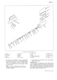
BRAKES S 6 1 Place the main cylinder in a vise with the outlet piston forward far enough to clear the stop screw holes facing up Place the check valve springs in the hole in the bottom of the front fluid reservoir Install outlet holes Be sure the springs are seated in the the stop screw bottom of the holes Place new rubber check valves 13 Install reservoir diaphragm in the reservoir cover over the springs being careful not to displace the and install t he cover on the main cylinder Push bail springs from the spring seats wire into position to secure the reservoir cover 2 Place new brass tube seats in the outlet holes Be Insmuuoon sure seats are not cocked as this would cause burrs to be turned up as the tube seats are pressed in 1 jgjtigglg th cgush r dl3 r gh the push red retamer Theadasa be1 1 tbnt ttn ut 1 e S SSem boi ood tfrg th nit Iago int lg togom oit 2 Push the retainer over the end of the main cylinder bottoms Remove the tube nut and cheek the outlet Assengble new pmt Over pushfod and pres it d W hole for loose burrs which might have been turned Htg p i O d retalmen Slide new mmmtmg gas h thtb t ddo Re atth s Ego o to goxogsgli soisoggiiiil Wn pe 1 3 sector the main cylinder to the firewall with mount 3 Put new secondary seals in the two grooves in the 4 gigxmgctsih usb d C1 t ol b k dl th end of the secondary piston assembly The seal d ter re ems O 8 ra epe E W1 which is nearest the end will have its lips facing to 5 r lgnzgctrtzagwgo 1 t th 1 d ward that end The seal in the second groove should 8 8 mes O Q mam y m sri have its lips facing toward the portion of the second 6 Flu m3 m cyhpder Iglselowglrs btoaluthm 1 4 Of res ary piston which contains the small compensating i1Q grni e Sr1 1 S ee 9 r 8 System as Out hoioo 1 1 e ion 4 Assemble a new primary seal protector and primary 7 ngcessafge ailggt 39 br g d 1 fr h 1 v S Out1 seal over the end of the secondary piston with the flat Smeo no G Orvmr aeele Op mma side of the seal seats against the seal protector and ec mn tho protootoy against the mango of the piston which 8 If manually bled recheck brake fluid level to insure contains the small compensating holes PFOPBF fluid 1 V 1 5 Assemble the new secondary seal into the groove on the push rod end of the primary piston The lips of BRAKE p pE D R BU QN AND vV C this seal should face toward the smallicompensating ASSEMBLY Fig 2 holes in the opposite end of the primary piston 6 Assemble the new primary seal protector and pri NOTE The brake pressure differentialwarn mary Soai on tho ond of the primary piston with the ing switch is a non adjustable non serv1ceable flat side of the seal seated against the seal protector Verve Ir dereetrve rr must be replaced and the protector against the flange on the piston Removal which contains the compensating holes 1 Disconnect battery cable 7 Assemble the Sprmg mtamer m one eng Of the pr 2 Disconnect electrical lead from switch assembly mary plsmn Sprmg and the Secondary plston Stop m 3 Place dr ra s below the switch to absorb an fluid the other end Place the end of the spring over the spilled ogringgromoval of Switch y egdtsoingfjo Iglfggriri l2 Ot oW1 o Sgggg YQ amy 4 Disconnect four hydraulic lines from connections at S a Z p p y switch lf necessary loosen line connections at main 8 Remove all cleaning liquid from the threaded hole in Cylinder to loosen hues Cover Open one ends with the pmmdry plsmn lace the Plstcm extensmn Screw clean lint free material to prevent foreign matter down through the secondary piston stop and the pri f t ol t mary spring retainer and screw it into the primary 5 Rmm en Brmg t 8 sys m d t h f piston umu it bottoms out ixoioifg moun 1ng screw an remove swi c rom 9 Coat the bore of the main cylinder with clean brake V fluid Coat the primary and secondary seals on the f fi0n Secondary piston with Clean brake fluid Insert the 1 Make sure new switch is clean and free of dust and secondary piston spring retainer into the secondary 1 t If d bt t h t h D 1 piston spring Place the retainer and spring down olguivalo yan3udry 1S i aS SW1 C m GC n Of over the end of the secondary piston until the re tainer locates inside of the lips of the primary cup 2 gllsistiiglgggox DOSIUOU and Secure to bracket wlth 10 Hold the master tv1i d r with the Gpep and of the 3 Remove protective material from open hydraulic bore down Push the secondary P1StOH into the bore brake lines and connect lines to switch If necessary 1 the Sprms Seats aaamst the closed and Of the tighten brake line connections at main cylinder bore 4 Connect switch electrical lead 11 Position the main cylinder in a vise with the open end 5 Connect battery cable of the bore up Coat the primary and secondary seal 6 Bleed the brake systems as outlined in this section on the primary piston with clean brake fluid Push the primary piston assembly spring end first into the bore of the main cylinder Hold the piston d0wn Bmke Wummg Llght Checkmg Pmcedure and snap the lock ring into position in the small groove in the I D of the bore 1 Determine if bulb is functioning by applying parking 12 Push the primary piston down to move the secondary brake then release CORVAIR SHOP MANUAL SUPPLEMENT

 Next
Next