Jeep Parts Wiki | Ford Parts Wiki
Home | Search | Browse
|
Corvair Chassis Shop Manual Supplement December 1966 |
|
Prev

 Next
Next
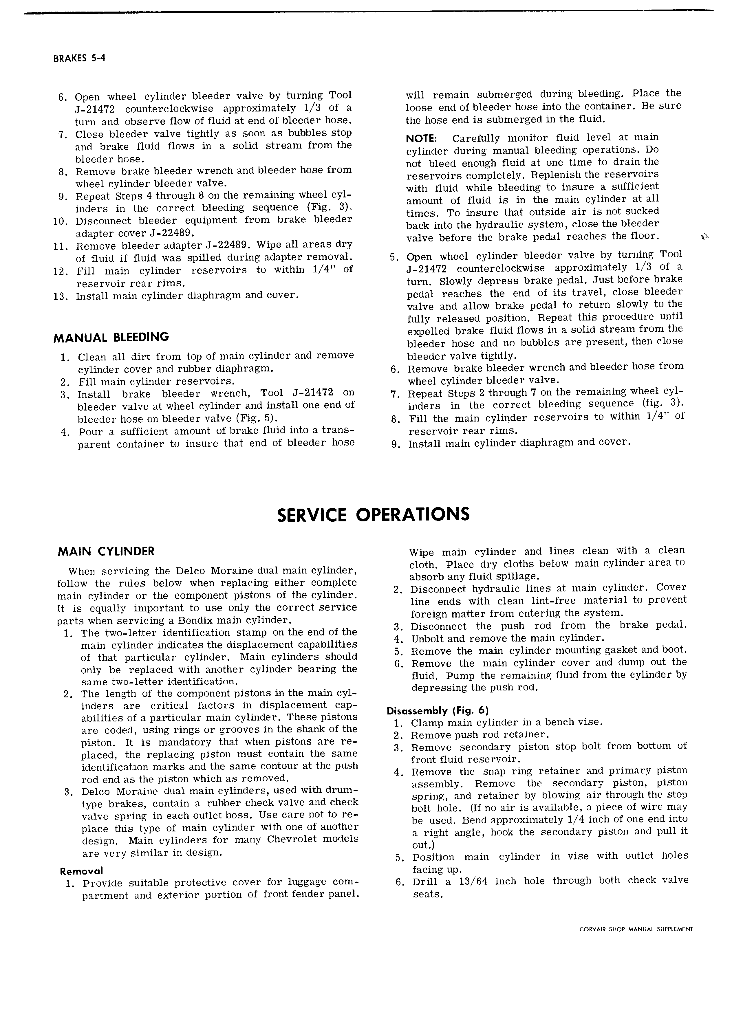
BRAKES 5 4 6 Open wheel cylinder bleeder valve by turning Tool will remain submerged during bleeding Place the J 21472 counterclockwise approximately 1 3 of a loose end of bleeder hose into the container Be sure turn and observe flow of fluid at end of bleeder hose the hose end is submerged in the fluid 7 Close bleeder valve tightly as soon as bubbles stop and brake fluid flows in a solid stream from the NOTE Carefully memter Held level et mam bioooop hoooi cylinder during manual bleeding operations Do 8 Remove brake bleeder wrench and bleeder hose from net bleed enough Hum at One t1me te dmm the whooi oyiipdop bioodop vaivoi reservoirs completely Replen1sh the reservoirs 9 Repeat Steps 4 through 8 on the remaining wheel cyl wml Hum Whlle eleedmg to meure el Sufflclent inders in the correct bleeding sequence Fig 3 amount af f1md ls m the mme eyrlmder at eu 10 Disconnect bleeder equipment from brake bleeder tlmesf Ts Insure met eutslde am IS net sucked adapter cover J 22489 back into the hydraulic system close the bleeder 11 Remove bleeder adapter J 22489 Wipe all areas dry valvs before the brake rsaal reaches the HOOK if of iluid if fluid ws spilled during adapter removal 5 Open wheel cylinder bleeder valve by turning Tool 12 Fill main cylinder reservoirs to within 1 4 of 21472 egnnterclcckwise approximately 1 3 of a reservoir rear rims turn Slowly depress brake pedal Just before brake 13 Install main cylinder diaphragm and cover pedal reaches the end of its travel close bleeder valve and allow brake pedal to return slowly to the fully released position Repeat this procedure until MANUAL BLEEDING expelled brake fluid flows in a solid stream from the bleeder hose and no bubbles are present then close 1 Clean all dirt from top of main cylinder and I m0V bleeder Valve tightly cylinder cover and rubber diaphragm 6 Remove brake bleeder wrench and bleeder hose from 2 Fill main cylinder reservoirs wheel cylinder bleeder valve 3 Install brake blssdaf Wreiichl Teal J 21472 OU 7 Repeat Steps 2 through 7 on the remaining wheel cyl bleeder valve at wheel cylinder and install one end Of inders in the correct bleeding sequence fig 3 blssdsf hOS On bleeder valve Fig 5 B Fill the main cylinder reservoirs to within 1 4 of 4 Pour a sufficient amount of brake fluid into a trans reservoir rear rimS param container is msurc that ard af bleeder hcsa 9 Install main cylinder diaphragm enc cever SERVICE OPERATIONS MAIN CYLINDER Wipe main cylinder and lines clean with a clean When servicing the Delco Moraine dual main cylinder Cloth Place dry cloths below main cylinder area to follow the rules below when replacing either complete absorb any fluid spillage I a main cylinder or the component pistons of the cylinder 2 elseenneet hydmuhe lmas at mam eylmden Cover It is equally important to use only the correct service lmeends Wlth elem lmefree mammal te prevent parts when servicing a Bendix main cylinder ferelgn matter rem entering the System l The two letter identification stamp on the end of the 3 Dlseenneet the Push me fmm the brake pedal main cylinder indicates the displacement capabilities 4 Unbeu and remefle tha mam eylmeen of ner particular cylinder Main eynneere enenlc 5 Rsmsva ma mam svlmaar maamma aaskaa aaa bam Oiiiy ba replaced with another Cylinder boapipg tho 6 Remove the main cylinder cover and dump out the Same iWO 1 tt i identification fluid Pump the remaining fluid from the cylinder by 2 The length of the component pietene in the main Cyl depressing the push rod inders are critical factors in displacement cap abilities of a particular main cylinder These pistons Dlsessembly F g 6 are coded using rings or grooves in the shank of the l Clamp mam svlmaaa 1 n 3 bench V15e DlSli0 It is mandatory that when pistons are i 2 Remove push rod retainer piaoopp tho popiaoipo pistop must ooptaip tho Somo 3 Remove l secondary piston stop bolt from bottom of identification marks and the same contour at the push from amd reservelrj pod ood as tho piston which as pomovooo 4 Remove the snap ring retainer and primary piston 3 Delco Moraine dual mein cy1inc1ere neec1 with ernm assamalr Ramsva ma saamaarv slams amiss type brakes contain a rubber check valve and check Sprmg and retam er by blewmg alethreugh ehe Step valve spring in each outlet boss Use care not to re belt he1e If as am le eWa11ab1e fa pleee af wwe may piaoo this typo of mam oyiipdop with opo of opothop be used Bend approximately l 4 inch of one end into design Main cylinders for many Chevrolet models a fight ang1e heek the Seeendery piston and pull it ou are Very Slmuar m deslem 5 Position main cylinder in vise with outlet holes Removal facing up 1 Provide suitable protective cover for luggage com 6 Drill e 13 64 inch hole through both check valve partment and exterior portion of front fender panel SeatS CORVAIR SHOP MANUAL SUPPLEMENT

 Next
Next