Jeep Parts Wiki | Ford Parts Wiki
Home | Search | Browse
|
Corvair Chassis Shop Manual Supplement December 1965 |
|
Prev
 Next
Next
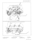
BODY AND CHASSIS ELECTRICAL I2 2 14 Install instrument cluster to console 8 Remove cluster from the console and transfer to a 15 Connect battery ground cable and check operation of suitable bench area for repair operations instruments Installation INSTRUMENT CLUSTER 1 Position instrument cluster assembly to console NOTE On Powerglide models attach shift lever Rem v Fig 3 mechanism to cluster assembly L Disconnect b8tt 1 Y around C bl9 2 Connect cluster wiring harness to instrument panel 2 Remove upper mast jacket support clamp Powerglide wiring narness fig 3 models Only 3 Install screws retaining cluster assembly to console 3 Remove light mid WiP SWit 3h bezel mills using T001 4 Connect speedometer cable to rear of speedometer J 21932 housing connect trip odometer if so equipped NOTE On Powerghde models remove Shift 5 l osition heater control to cluster and install retain lever knob mg S rel VS 6 Install light and wiper switch bezel retaining nuts 4 R m0V h 3t I OY ai Conditmning tr 1r t i i g On Powerglide models install shift lever knob and on screws and allow control to hang below instrument A C models install air outlet console On A C models remove air outlet from 7 Install mast jacket upper support c1amp P 1 l 8 Connect battery ground cable and check operation of 5 Disconnect speedometer cable at rear of speedom cluster assembly eter housing If so equipped disconnect trip 0d m 1 WIRING HARNESS 6 glenigvgolisgliws retammg mstrument cluster llSS m The wiring harness assemblies remain essentially the 7 Pilll instrument cluster assembly forward from con Same as 1965 except for ll new color Code common to all vehicles The color of the wire designates a particular Sole wld dlscolmect 1 S g hllmesslllom circuit while the harness title indicates the type of panel wlrmg harness at mulllple dlsccmlecl llg 3 harness single or multiple wire and also describes the NOTE On Powerglide models remove shift location of the harness Composite wiring diagrams for lever mechanism from rear of cluster housing all models are included in Figures 4 thru 7 CHEVROLET CORVAIR SHOP MANUAL