Jeep Parts Wiki | Ford Parts Wiki
Home | Search | Browse
|
Corvair Chassis Shop Manual Supplement December 1965 |
|
Prev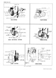
 Next
Next
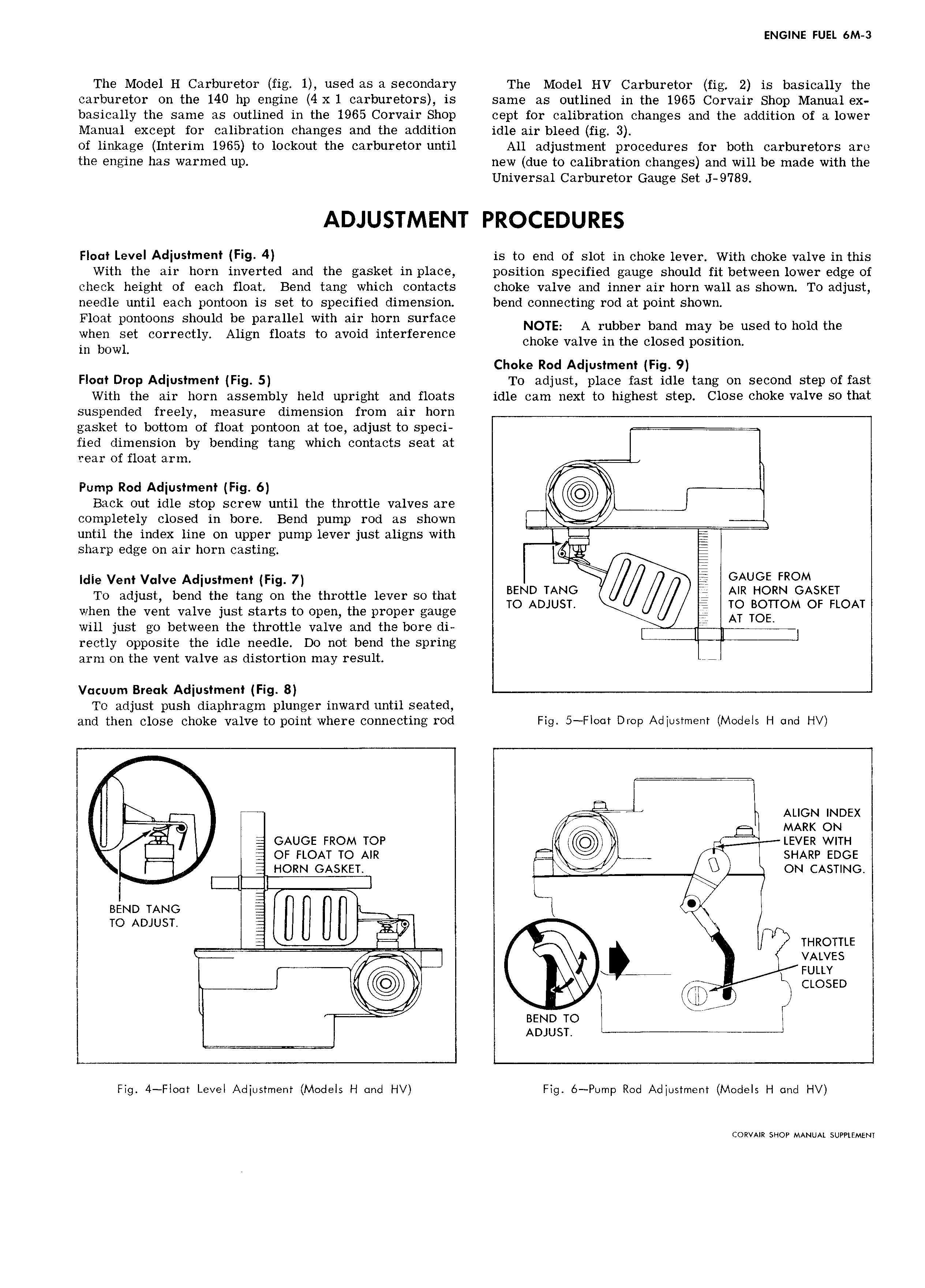
ENGINE FUEL 6M 3 The Model H Carburetor fig 1 used as a secondary The Model HV Carburetor fig 2 is basically the carburetor on the 140 hp engine 4 xl carburetors is same as outlined in the 1965 Corvair Shop Manual ex basically the same as outlined in the 1965 Corvair Shop cept for calibration changes and the addition of a lower Manual except for calibration changes and the addition idle air bleed fig 3 of linkage Interim 1965 to lockout the carburetor until All adjustment procedures for both carburetors are the engine has warmed up new due to calibration changes and will be made with the Universal Carburetor Gauge Set 9 789 ADJUSTMENT PROCEDURES Float Level Adjustment Fig 4 is to end of slot in choke lever With choke valve in this With the air horn inverted and the gasket in place position specified gauge should fit between lower edge of check height of each float Bend tang which contacts choke valve and inner air horn wall as shown To adjust needle until each pontoon is set to specified dimension bend connecting rod at point shown Float pontoons should be parallel with air horn surface NOTE A rubber band may be used to hold the when set correctly Align floats to avoid mterference in bowl choke valve in the closed position Choke Rod Adjustment Fig 9 Float Drop Adjustment Fig 5 To adjust place fast idle tang on second step of fast With the air horn assembly held upright and floats idle cam next to highest step Close choke valve so that suspended freely measure dimension from air horn gasket to bottom of float pontoon at toe adjust to speci fied dimension by bending tang which contacts seat at rear of float arm r x I Pump Rod Adjustment Fig 6 Back out idle stop screw until the throttle valves are completely closed in bore Bend pump rod as shown until the index line on upper pump lever just aligns with E E sharp edge on air horn casting fyy Idle Vent Valve Adjustment Fig 7 f GAUGE FROM To adjust bend the tang on the throttle lever so that BEND TANG M NR HORN GASKET TO ADJUST TO BOTTOM OF FLOAT when the vent valve just starts to open the proper gauge AT TOE will just go between the throttle valve and the bore di I rectly opposite the idle needle Do not bend the spring arm on the vent valve as distortion may result are Vacuum Break Adjustment Fig 8 To adjust push diaphragm plunger inward until seated and then close choke valve to point where connecting rod Fig 5 FIoot Drop Adjustment Models H and HV I I ALIGN INDEX Q MARK ON I t GAUGE FROM TOP I LEVER WITH ot FLOAT TO AIR c A I SHARP EDGE HORN GASKET J ON CASTING I Ln 5 BEND TANG I U jj O TO ADJUST 9 X g A I THROTTLE VALVES I r Q Euttv 4 gg In CLOSED I I nav Q I BEND TO I ADJUST Fig 4 Flo t Level Adjustment Models H and HV Fig 6 Pump Rod Adjustment Models H and HV CORVAIR SHOP MANUAL SUPPLEMENT