Jeep Parts Wiki | Ford Parts Wiki
Home | Search | Browse
|
Corvair Chassis Shop Manual Supplement December 1965 |
|
Prev
 Next
Next
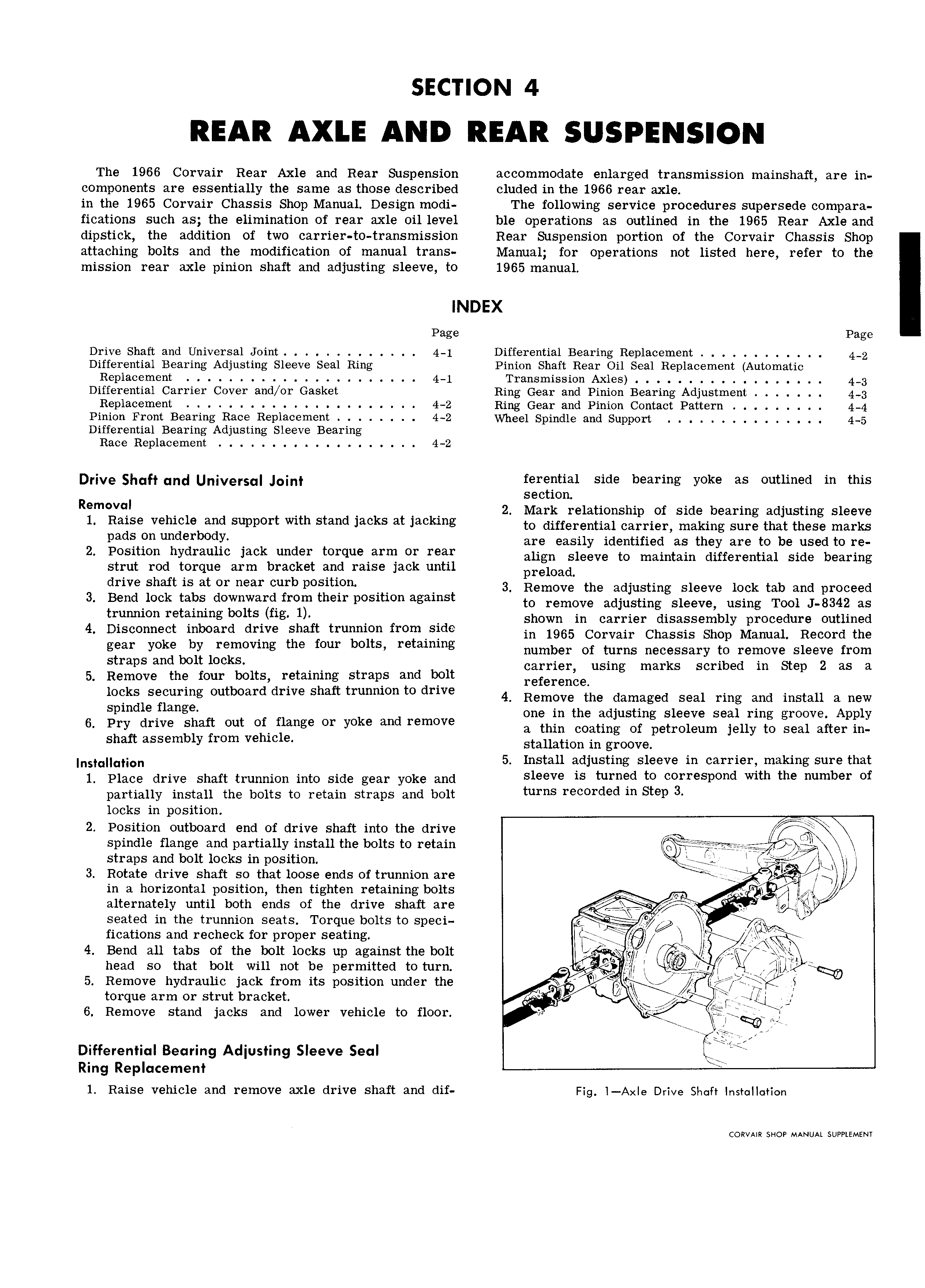
The 1966 Corvair Rear Axle and Rear Suspension accommodate enlarged transmission mainshaft are in components are essentially the same as those described cluded in the 1966 rear axle in the 1965 Corvair Chassis Shop Manual Design modi The following service procedures supersede compara fications such as the elimination of rear axle oil level ble operations as outlined in the 1965 Rear Axle and dipstick the addition of two carrier to transmission Rear Suspension portion of the Corvair Chassis Shop attaching bolts and the modification of manual trans Manual for operations not listed here refer to the mission rear axle pinion shaft and adjusting sleeve to 1965 manual INDEX Page Page Drive Shaft and Universal Joint 4 1 Differential Bearing Replacement 4 2 Differential Bearing Adjusting Sleeve Seal Ring Pinion Shaft Rear Oil Seal Replacement Automatic Replacement 4 1 Transmission Axles 4 3 Differential Carrier Cover and or Gasket Ring Gear and Pinion Bearing Adjustment 4 3 Replacement 4 2 Ring Gear and Pinion Contact Pattern 4 4 Pinion Front Bearing Race Replacement 4 2 Wheel Spindle and Support 4 5 Differential Bearing Adjusting Sleeve Bearing Race Replacement 4 2 Drive Shuff and Un vers Joint ferential side bearing yoke as outlined in this section Re l 2 Mark relationship of side bearing adjusting sleeve 1 Reuse vehicle and support with Stand jeeks at looking to differential carrier making sure that these marks pads on underbodr are easily identified as they are to be used to re 2 Position nyureuue jack under torquerrrn or reer align sleeve to maintain differential side bearing strut rod torque arm bracket and raise jack until pr 1Oad drive snerr is at or near curb positron 3 Remove the adjusting sleeve lock tab and proceed 3 Bend lock tabs downward from their position against to remove adjusting Sleeve using TOO1 J 8342 as trunnion reteuung b 1tS f1g 1 shown in carrier disassembly procedure outlined 4 Disconnect inboard drive shaft trunnion fromlside in 1965 Cowan Chassis Shop Manual Record the gear Yoke by removmg the four bO1tS retemms number of turns necessary to remove sleeve from Straps and 1 1 kS carrier using marks scribed in Step 2 as a 5 Remove the four bolts retaining straps and bolt reference locks securing outboard drive shaft trunnion to drive 4 Remove the damaged Seal ring and install 3 new spindle flange one in the adjusting sleeve seal ring groove Apply haft t of flan e or oke and remove o pry drwe S Ou g y a thin coating of petroleum jelly to seal after in shaft assembly from vehicle Stauation in groove lnstallation 5 Install adjusting sleeve in carrier making sure that 1 Place drive shaft trunnion into side gear yoke and Sleeve ls turned to eorrespond wltn tne mb r or partially install the bolts to retain straps and bolt turns r rd d m Step 3 locks in position 2 Position outboard end of drive shaft into the drive X spindle flange and partially install the bolts to retain qv straps and bolt locks in position gQl I Jig 3 Rotate drive shaft so that loose ends of trunnion are K I j in a horizontal position then tighten retaining bolts O 5 alternately until both ends of the drive shaft are seated in the trunnion seats Torque bolts to speci jj isi fications and recheck for proper seating Q J LC ii 4 Bend all tabs of the bolt locks up against the bolt g W g i xp l head so that bolt will not be permitted to turn O 4 g jll l f 5 Remove hydraulic jack from its position under the lr 5 t I O Q l 1rT 1 orque arm or strut bracket N gh j f K J h cle to floor 5 6 Remove stand jacks and lower ve 1 g J WQG Differential Bearing Adjusting Sleeve Seal gies Ring Replacement 1 Raise vehicle and remove axle drive shaft and dif Fig l Axle Drive Shaft Insmllution CORVAIR SHOP MANUAL SUPPLEMENT