Jeep Parts Wiki | Ford Parts Wiki
Home | Search | Browse | Marketplace | Messages | FAQ | Guest
Prev

 Next
Next
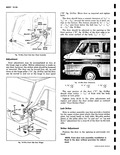
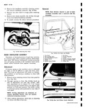
1 Position striker assembly on pillar so outer face of lock rotor swings into the striker assembly with 160 clearance to the striker inner face This adjustment can be made by using the 060 and 120 spacers as required fig 10 39a O6 OR 12 SPACERS AS REQUIRED LOCK ROTOR BODY LOCK HOUSING PILLAR 16 CLEARANCE I STRIKER INNER FACE STRIKER ASS Y Fig 10 39a Striker Plate Spacer Installation 2 Place the upper and lower door lock striker plates between the striker or striker shims if required and the body lock pillar 3 Position the upper plate so the two tabs project into the two slots in the rear face of the striker assembly This prevents the plate from rotating I during assembly Also position the lower plate so the plate outline matches the depression on the striker assembly mounting face fig 10 40a UPPER STRIKER PLATE FIT PLATE TABS STRIKER ASS Y INTO STRIKER SLOTS DEPRESSION ON LOCK STRIKER MTG FACE PILLAR SPACERS AS REQ D LOWER STRIKER PLATE Fig 10 40a Location of Striker Plates 4 Attach striker with shims and adjusting plates to pillar and position as follows a Lateral adjustment position striker assembly laterally so that in the locked position the door outer surface is flush to the pillar surface within 1 1 g at door rear edge fig 10 41a NOTE As an aid to striker adjustment out line the striker in pencil or crayon for use as a base for adjustment 1 BODY LOCK PILLAR DOOR REAR EDGE FLUSH WITHIN 06 Fig 10 41a Door Rear Edge Surface location b Vertical adjustment Position striker vertically so that the lock rotor and rotor housing swings smoothly into the opening between the striker gear teeth and the striker sliding wedge block fig 10 42a NOTE The door assembly should not be raised as the teeth engage and the lock rotor housing must dear the striker housing as the lock enters the striker LOCK ROTOR STRIKER ASS Y HOUSING SIIDING WEDGE BLOCK DOOR SWING z PILLAR STRIKER LINE MTG DEPRESSION Fig 10 42a lock Rotor Position in Striker DOOR CHECK The door check is mounted just below the upper hinge assembly and consists of two assemblies the door check arm which is mounted in the hinge pillar and the door check bracket which is mounted on the door fig 10 36a Removal and Installation 1 Remove pin from door check arm to bracket fig 10 36a 2 Remove four headlamp door retaining screws and remove door CORVAIR SHOP MANUAL

 Next
Next