Jeep Parts Wiki | Ford Parts Wiki
Home | Search | Browse | Marketplace | Messages | FAQ | Guest
Prev

 Next
Next
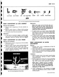
CAUTION Exercise care when releasing tension from rods after removal of pin as torque rods may be under considerable tension 4 Disengage each torque rod from movable portion of affected hinge and remove rods Installation 1 Position appropriate torque rod behind retaining tab on movable portion of affected hinge as shown in Figure 10 14 and engage rod in notches in lower portion of hin e assembly and in torque rod retainer fig 10 15 HINGE NOTCHES TORQUE RODS I w PIN y TORQUE ROD RETAINER O TABS Fig 10 15 Front Compartment Lid Torque Rods 2 Tension torque rods as outlined in Step 3 of the removal procedure and install pin in previously marked hole in torque rod retainer NOTE Rotate pin after installation to insure pin is locked in hole 3 Lubricate torque rod bearing points as outlined under Body Lubrication in Section 2 Adjustments The amount of effort required to open and close the front compartment lid is determined by the position of the retaining pin in the torque rod retainer If the retaining pin is located in the hole farthest rearward the amount of effort required to open the lid is the least and the amount of effort required to close the lid is the greatest If the retaining pin is located in the hole farthest forward the amount of effort required to open the lid is the greatest and the amount of effort required to close the lid is the least FRONT COMPARTMENT LID LOCK CYLINDER ASSEMBLY Removal and Installation 1 Open front compartment lid and disengage retainer fig 10 16 securing lock cylinder assembly to front end panel and remove assembly 2 To install replace sealing gasket if necessary engage end of lock cylinder shaft in lock and reverse removal procedure f LOCK ASSEMBLY LOCK CYLINDER RETAINER r a y e SCREWS Fig 10 16 Front Compartment Lid Lock Disassembly and Assembly 1 Remove lock cylinder assembly from body 2 Disengage return spring fig 10 17 from lock cylinder case and remove spring RETURN SPRING TAB Fig 10 17 Front Compartment Lid Lock Cylinder Assembly 3 Disengage retainer tab fig 10 17 from lock cylinder case then remove retainer shaft and lock cylinder assembly fig 10 18 4 Disengage dust cover spring from end of dust cover shaft and remove spring and cover fig 10 18 NOTE Dust cover may be removed without removing other components of the lock cylinder assembly 5 To install reverse the removal procedure

 Next
Next