Jeep Parts Wiki | Ford Parts Wiki
Home | Search | Browse | Marketplace | Messages | FAQ | Guest
Prev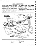
 Next
Next
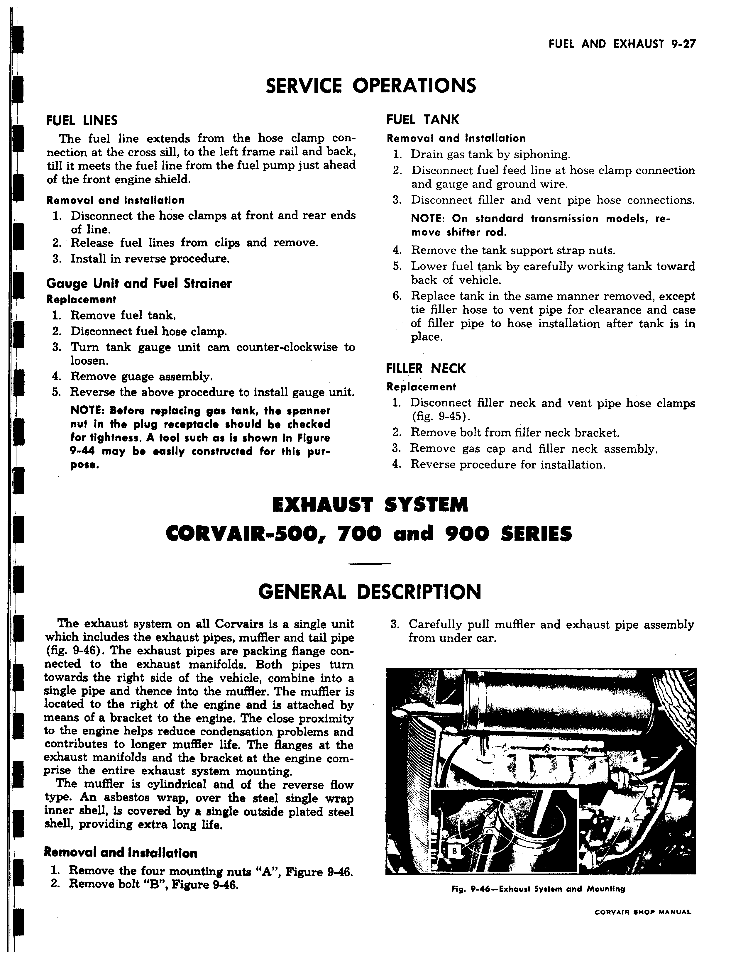
SERVICE I FUEL LINES The fuel line extends from the hose clamp connection at the cross sill to the left frame rail and back till it meets the fuel line from the fuel pump just ahead of the front engine shield Removal and Installation 1 Disconnect the hose clamps at front and rear ends of line 2 Release fuel lines from clips and remove 3 Install in reverse procedure Gauge Unit and Fuel Strainer Replacement 1 Remove fuel tank 2 Disconnect fuel hose clamp 3 Turn tank gauge unit cam counter clockwise to loosen 4 Remove guage assembly 5 Reverse the above procedure to install gauge unit NOTE Before replacing gas tank the spanner nut in the plug receptacle should be checked for tightness A tool such a is shown in Figure 9 44 may be easily constructed for this purpose EXHAUs CORVAIR 500 71 GENERAL The exhaust system on all Corvairs is a single unit which includes the exhaust pipes muffler and tail pipe fig 9 46 The exhaust pipes are packing flange connected to the exhaust manifolds Both pipes turn towards the right side of the vehicle combine into a single pipe and thence into the muffler The muffler is located to the right of the engine and is attached by means of a bracket to the engine The close proximity to the engine helps reduce condensation problems and contributes to longer muffler life The flanges at the exhaust manifolds and the bracket at the engine comprise the entire exhaust system mounting The muffler is cylindrical and of the reverse flow type An asbestos wrap over the steel single wrap inner shell is covered by a single outside plated steel shell providing extra long life Removal and Installation 1 Remove the four mounting nuts A Figure 9 46 2 Remove bolt B Figure 9 46 PERATIONS FUEL TANK Removal and installation 1 Drain gas tank by siphoning 2 Disconnect fuel feed line at hose clamp connection and gauge and ground wire 3 Disconnect filler and vent pipe hose connections NOTE On standard transmission models remove shifter rod 4 Remove the tank support strap nuts 5 Lower fuel tank by carefully working tank toward back of vehicle 6 Replace tank in the same manner removed except tie filler hose to vent pipe for clearance and case of filler pipe to hose installation after tank is in place FILLER NECK Replacement 1 Disconnect filler neck and vent pipe hose clamps fig 9 45 2 Remove bolt from filler neck bracket 3 Remove gas cap and filler neck assembly 4 Reverse procedure for installation IT SYSTEM O and 900 SERIES DESCRIPTION 3 Carefully pull muffler and exhaust pipe assembly from under car r AF 9 s v sq r Fig 9 46 Exhaust SysNm and Mounting