Jeep Parts Wiki | Ford Parts Wiki
Home | Search | Browse
Prev

 Next
Next
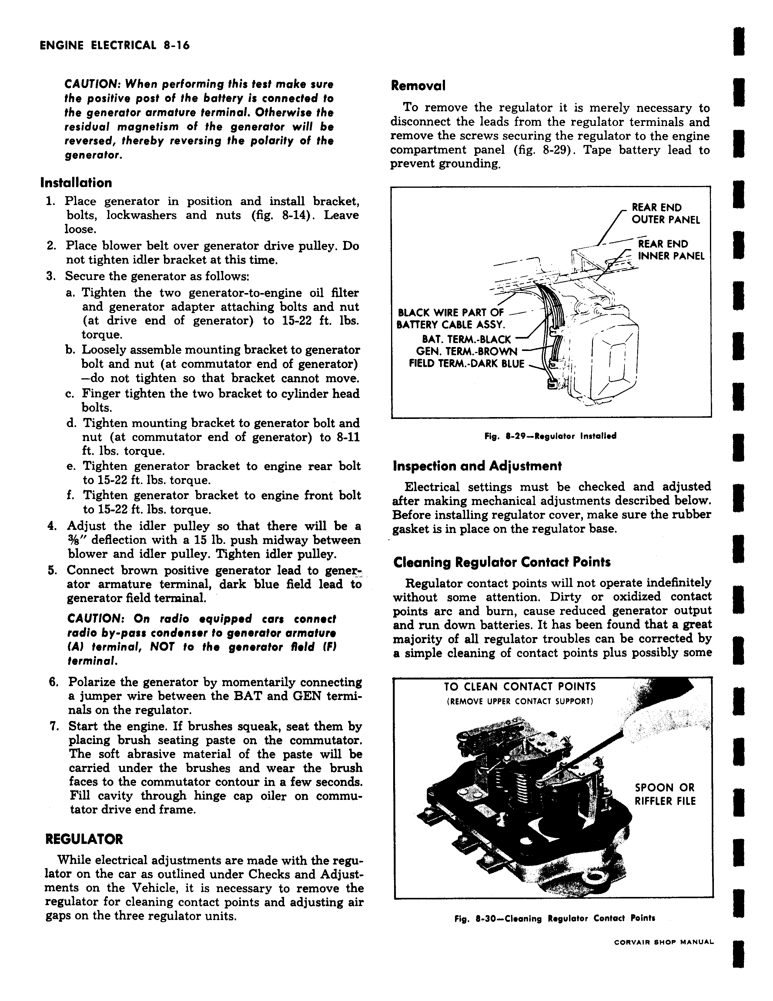
CAUTION When performing this teat make sure the positive post of the battery is connected to the generator armature terminal Otherwise the residual magnetism of the generator will be reversed thereby reversing the polarity of the generator Installation 1 Place generator in position and install bracket bolts lockwashers and nuts fig 8 14 Leave loose 2 Place blower belt over generator drive pulley Do not tighten idler bracket at this time 3 Secure the generator as follows a Tighten the two generator to engine oil filter and generator adapter attaching bolts and nut at drive end of generator to 15 22 ft lbs torque b Loosely assemble mounting bracket to generator bolt and nut at commutator end of generator do not tighten so that bracket cannot move c Finger tighten the two bracket to cylinder head bolts d Tighten mounting bracket to generator bolt and nut at commutator end of generator to 8 11 ft lbs torque e Tighten generator bracket to engine rear bolt to 15 22 ft lbs torque f Tighten generator bracket to engine front bolt to 15 22 ft lbs torque 4 Adjust the idler pulley so that there will be a 3 s deflection with a 15 lb push midway between blower and idler pulley Tighten idler pulley 5 Connect brown positive generator lead to generator armature terminal dark blue field lead to generator field terminal CAUTION On radio equipped car connect radio by pass condenser to generator armature A terminal NOT to the generator field IF terminal 6 Polarize the generator by momentarily connecting a jumper wire between the BAT and GEN terminals on the regulator Start the engine If brushes squeak seat them by placing brush seating paste on the commutator The soft abrasive material of the paste will be carried under the brushes and wear the brush faces to the commutator contour in a few seconds Fill cavity through hinge cap oiler on commutator drive end frame REGULATOR While electrical adjustments are made with the regulator on the car as outlined under Checks and Adjustments on the Vehicle it is necessary to remove the regulator for cleaning contact points and adjusting air gaps on the three regulator units Removal To remove the regulator it is merely necessary to disconnect the leads from the regulator terminals and remove the screws securing the regulator to the engine compartment panel fig 8 29 Tape battery lead to prevent grounding REAR END OUTER PANEL REAR END INNER PANEL l r BLACK WIRE PART OF BATTERY CABLE ASSY BAT TERM BLACK GEN TERM BROWN FIELD TERM DARK BLUE v Fig 8 29 Regulator installed Inspection and Adjustment Electrical settings must be checked and adjusted after making mechanical adjustments described below Before installing regulator cover make sure the rubber gasket is in place on the regulator base Cleaning Regulator Contact Points Regulator contact points will not operate indefinitely without some attention Dirty or oxidized contact points arc and burn cause reduced generator output and run down batteries It has been found that a great majority of all regulator troubles can be corrected by a simple cleaning of contact points plus possibly some TO CLEAN CONTACT POINTS REMOVE UPPER CONTACT SUPPORT SPOON OR m RIFFLER FILE Fig 8 30 Cleaning R gulator Contact Points CffRV IR BNOP MANUAL

 Next
Next